Shaft lever part locking apparatus

A technology for locking devices and parts, applied in the direction of workpiece clamping devices, positioning devices, auxiliary devices, etc., can solve problems such as inconvenient use, achieve good results, novel structural design, and improve locking efficiency

Inactive Publication Date: 2015-09-16
WUHU CHUANGZHI MACHINERY TECH
View PDF6 Cites 4 Cited by
  • Summary
  • Abstract
  • Description
  • Claims
  • Application Information

AI Technical Summary

Problems solved by technology

[0003] In the process of mechanical machining, there are relatively many shaft parts, which often need to be clamped and positioned, which is quite inconvenient to use

Method used


Image

  • Shaft lever part locking apparatus

Examples


Embodiment Construction

[0013] See attached picture:

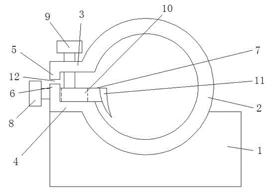
[0014] The locking device for shaft parts includes a split ring 2 installed on the fixed seat 1. The outer wall of the open end of the split ring 2 is provided with a parallel upper extension plate 3 and a lower extension plate 4. The ends of the two extension plates are folded opposite to each other. The upper vertical plate 5 and the lower vertical plate 6 are bent, and the top plate 7 is slidably installed on the upper end of the lower extension plate 4. The end of the top plate 7 is fixed with the horizontal locking bolt 8, and the horizontal locking bolt 8 is screwed through the lower vertical plate 6; The upper end surface of the upper extension plate 4 is screwed with a longitudinal locking bolt 9 , and the front end of the longitudinal locking bolt 9 is screwed and extends into the lower extension plate 4 .

[0015] A strip-shaped hole 10 along the horizontal direction is opened in the middle of the top plate 7 , and the longitudinal lock...


PUM


Abstract

The invention discloses a shaft lever part locking apparatus comprising a split ring arranged on a fixing seat. The outer wall of an opening end of the split ring is provided with an upper extension plate and a lower extension plate parallel to the upper extension plate; the tail ends of the two extension plates are relatively bent to form an upper vertical plate and a lower vertical plate; the upper end surface of the lower extension plate is slideably provided with a top plate; the tial end of the top plate and a transverse locking bolt are fixed; the transverse locking bolt screws and passes through the lower vertical plate; a longitudinal locking bolt is screwed in the upper end surface of the upper extension plate; and the front end of the longitudinal locking bolt is screwed into the lower extension plate. The shaft lever part locking apparatus is structured with novelty; and with the upper locking bolt, the lower locking bolt and the top plate matched with the split ring and the opening end, the shaft lever part can be quickly positioned, so locking efficiency can be improved and great practical use effect can be achieved.

Description

technical field [0001] The invention relates to a clamp, in particular to a locking device for shaft-like parts. Background technique [0002] A fixture is a device used to fix the processing object in the process of mechanical manufacturing so that it occupies the correct position for construction or inspection. Also known as fixture. In a broad sense, any process in the process, the device used to install the workpiece quickly, conveniently and safely, can be called a fixture. Such as welding fixtures, inspection fixtures, assembly fixtures, machine tool fixtures, etc. [0003] In the process of mechanical machining, there are relatively many shaft parts, which often need to be clamped and positioned, which is quite inconvenient to use. Contents of the invention [0004] In order to make up for the problems in the prior art, the purpose of the present invention is to provide a locking device for shaft-like parts, which has a novel structural design, can quickly and c...

Claims


Application Information

Patent Timeline
Patent Type & Authority Applications(China)
IPC IPC(8): B23Q3/00B25B11/00B25B11/02B23K37/04
CPCB23Q3/00B23K37/04B25B11/00B25B11/02
Inventor 赵开胜
Owner WUHU CHUANGZHI MACHINERY TECH
Why Eureka
Try Eureka