Supercharge Your Innovation With Domain-Expert AI Agents!

support device

A technology for supporting devices and supporting components, which is applied in the direction of workpiece clamping devices, assembly machines, metal processing, etc., can solve the problems of workpiece support stability or support strength reduction, cost increase, and workbench space occupation, so as to ensure the support strength Effect

Active Publication Date: 2017-09-29
JATCO LTD
View PDF1 Cites 0 Cited by
  • Summary
  • Abstract
  • Description
  • Claims
  • Application Information

AI Technical Summary

Problems solved by technology

[0011] However, since the arm is disposed at a position away from the upper surface of the table, and the portion of the arm where the positioning pin is provided can be displaced in a direction approaching the table (the axial direction of the rotation shaft), the workpiece with the positioning pin engaged Decreased bearing stability or bearing strength
[0012] In addition, because each position adjustment mechanism needs to be provided with a locking mechanism, when a plurality of positioning pins are arranged on the workbench, the cost will increase accordingly, and the space on the workbench will be occupied.

Method used


Image

  • support device
  • support device
  • support device

Examples


Embodiment Construction

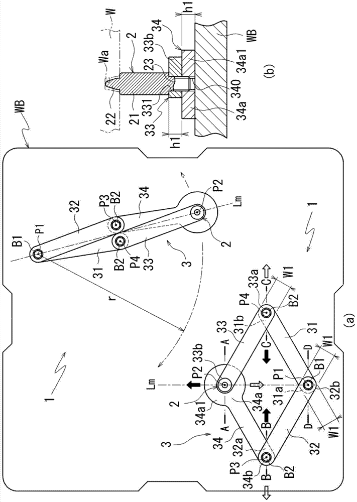
[0127] figure 1 It is a figure explaining the support apparatus 1 of 1st Embodiment, (a) is a plan view of the workbench WB provided with the support apparatus 1, (b) is AA sectional drawing of (a).

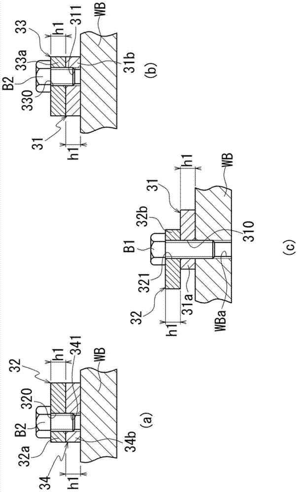
[0128] figure 2 It is a sectional view of the main part of the position adjustment mechanism 3 of the support device 1, (a) is figure 1 The BB profile, (b) is figure 1 The C-C sectional view of , (c) is figure 1 The D-D cross-section.

[0129] The table WB conveyed on the conveyor belt of the assembly line of the automatic transmission is a rectangular plate-shaped member in plan view, and a work table for holding the workpiece W on the table is provided in a state of being supported by the position adjustment mechanism 3 . Locating pin 2 at the specified position on the WB.

[0130] The position adjustment mechanism 3 is provided to hold the positioning pin 2 at a desired position on the table WB, and two are provided at intervals in the diagonal direction of the table WB....


PUM


Abstract

A support device that holds the positioning pin in the desired position with a simpler structure. The support device (1) supports the workpiece (W) at a predetermined position on the workbench (WB), and is configured such that a plurality of link members (31 to 34) are connected by connecting members (bolts B1, B2, bolt portion 23). The annular position adjustment mechanism (3) is placed on the workbench, and one of the connection points (P1) of the link members (31 to 34) is supported on the workbench. In addition to the support One of the connection points (P2) other than the connection point of the workbench is provided with a positioning pin (2) (engagement member) that engages with the workpiece. When the position of the positioning pin of the workbench is changed, the connection is weakened. The connecting force of the components enables the connecting rod components connected at the connecting point to rotate relative to each other. When the position of the positioning pin is fixed, the connecting force of the connecting component is increased so that the connecting rod components connected at the connecting point cannot rotate relative to each other.

Description

technical field [0001] The invention relates to a supporting device for supporting workpieces on a worktable. Background technique [0002] In an assembly line of an automatic transmission for a vehicle, a table (pallet) on which components (workpieces) of the automatic transmission are placed is transported on a conveyor belt and supplied to an assembly process of the components. [0003] Because the table vibrates when it is conveyed on the conveyor belt, large components such as gearboxes are held at predetermined positions on the table by the support members provided on the table, and do not fall off the table during transportation. [0004] Patent Document 1: (Japanese) Unexamined Patent Application Publication No. 2001-121375 [0005] Patent Document 1 discloses a workpiece support device for holding a workpiece at a predetermined position, which includes: a positioning pin (support member) fitted into a reference hole provided in the workpiece, a position adjustment ...

Claims


Application Information

Patent Timeline
Patent Type & Authority Patents(China)
IPC IPC(8): B25B11/00B23P21/00
CPCB23P19/006B25B11/02
Inventor 田中正志小川浩史永田裕一郎
Owner JATCO LTD
Features
  • R&D
  • Intellectual Property
  • Life Sciences
  • Materials
  • Tech Scout
  • Unparalleled Data Quality
  • Higher Quality Content
  • 60% Fewer Hallucinations
Learn More