
Feeder roller

A feeder and roller technology, applied in the direction of conveyors, mechanical conveyors, shafts and bearings, etc., can solve the problems of large particle size of broken materials, frequent maintenance, poor lubrication, etc., to prolong service life, improve mechanical performance, reduce The effect of maintenance frequency

Inactive Publication Date: 2015-09-16
NANTONG UNITED HEAVY MACHINERY
View PDF7 Cites 2 Cited by
  • Summary
  • Abstract
  • Description
  • Claims
  • Application Information

AI Technical Summary

Problems solved by technology

[0002] Since the feeder in the current prior art is put into operation, the maintenance rate is high and the normal production is often not possible. The reason is that its structure is composed of a transmission shaft, a steel sleeve, Composed of copper sleeves, inner and outer chain plates and rollers, due to the large particle size, heavy load, and poor lubrication of the crushed materials during operation, the softer copper sleeves are worn and deformed by extrusion and elongation in a few days, and the connecting chain plates are often pushed off, while the original The oil filling hole is often blocked by the deformed copper sleeve, resulting in the inability of grease to enter, difficulty in lubrication, frequent maintenance and heavy labor

Method used


Image

  • Feeder roller

Examples


Embodiment

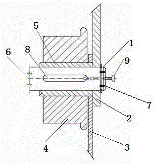
[0019] Such as figure 1 As shown, a feeder roller in this embodiment includes a clamping plate 1, an outer chain plate 2, an inner chain plate 3, a roller 4, a steel sleeve 5, a pin shaft 6, and a fastening screw 7; The fixed screw 7 is fixed on the end of the pin shaft 6; the outer chain plate 2 and the inner chain plate 3 are arranged parallel to each other; the inner chain plate 3 is stuck between the roller 4 and the steel sleeve 5. An oil groove 8 is also provided on the steel sleeve 5 . An oil cup 9 is also provided at the end of the pin shaft 6 . The material of roller 4 and steel sleeve 5 is cast steel.


PUM


Abstract

The invention discloses a feeder roller which comprises a clamping plate, an outer chain plate, an inner chain plate, a roller body, a steel sleeve, a pin shaft and fastening screws. The clamping plate is fixed to one end of the pin shaft through the fastening screws. The outer chain plate and the inner chain plate are parallel. The inner chain plate is clamped between the roller body and the steel sleeve. The feeder roller is simple in design, prevents oil filing ports from being blocked, and is good in lubrication effect, more resistant to abrasion in long-term operation, and longer in service life. Lots of experiments show that the roller needs to be maintained and replaced only after being abraded to limit, the maintenance frequency is greatly reduced, and production is guaranteed.

Description

technical field [0001] The invention relates to the field of feeders, in particular to a feeder roller. Background technique [0002] Since the current feeder in the prior art has been put into operation, it has a high maintenance rate and often fails to produce normally. The reason is that its structure is composed of a transmission shaft, steel sleeve, copper sleeve, inner and outer chain plates and rollers. Large particle size, heavy load, poor lubrication, within a few days the softer copper sleeve wears and deforms and is squeezed and elongated, often knocking off the connecting chain plate, and the original oil filling hole is often blocked by the deformed copper sleeve, resulting in the grease not getting in , Lubrication is difficult, frequent maintenance, heavy labor. Contents of the invention [0003] The technical problem to be solved by the invention [0004] The object of the present invention is to overcome the above-mentioned technical deficiencies, and p...

Claims


Application Information

Patent Timeline
Patent Type & Authority Applications(China)
IPC IPC(8): B65G35/00F16C13/00
Inventor 夏盛伯徐瑞军戎世根郭有荣
Owner NANTONG UNITED HEAVY MACHINERY
Learn More