
Spiral jet aerator

A jet aeration and spiral technology, which is applied in water aeration, sustainable biological treatment, water/sludge/sewage treatment, etc., can solve the problems of low dissolved air efficiency, etc. Effect

Inactive Publication Date: 2015-09-16
SICHUAN KAIMING MACHINERY MFG
View PDF12 Cites 4 Cited by
  • Summary
  • Abstract
  • Description
  • Claims
  • Application Information

AI Technical Summary

Problems solved by technology

[0010] In order to solve the problem of low efficiency of dissolved air in the existing aerator, the present invention provides a spiral jet aerator, which can improve the efficiency of dissolved air, thereby improving the effect of sewage treatment

Method used


Image

  • Spiral jet aerator
  • Spiral jet aerator

Examples


Embodiment 1

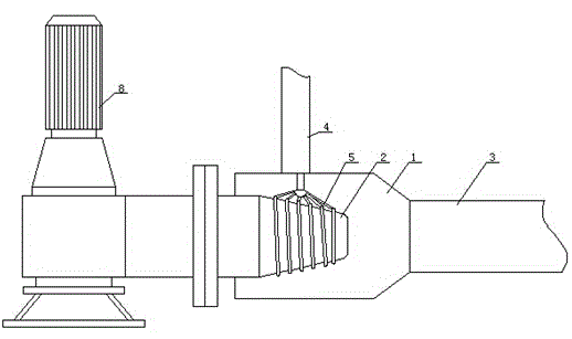
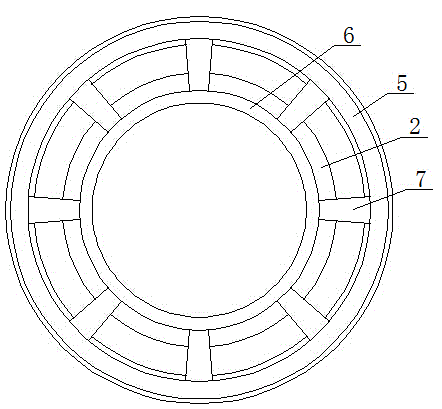
[0027] The spiral jet aerator of this embodiment includes a water pump, the water pump is connected with an aerator, the aerator includes a suction chamber and a nozzle, the nozzle is inserted from one end of the suction chamber, and the suction The other end of the air chamber is connected with a throat, and the suction chamber is also connected with a suction pipe. The inside of the nozzle is provided with a spiral deflector, and a number of through holes are opened on the nozzle between adjacent spiral deflectors. , the suction pipe is connected with at least two air intake branch pipes, the air intake branch pipes are sleeved on the periphery of the nozzle, the air intake branch pipes are evenly provided with air inlets with the same number of through holes, and the air inlets It communicates with the through hole through the pipeline.

Embodiment 2

[0029] The spiral jet aerator of this embodiment includes a water pump, the water pump is connected with an aerator, the aerator includes a suction chamber and a nozzle, the nozzle is inserted from one end of the suction chamber, and the suction The other end of the air chamber is connected with a throat, and the suction chamber is also connected with a suction pipe. The inside of the nozzle is provided with a spiral deflector, and a number of through holes are opened on the nozzle between adjacent spiral deflectors. , the suction pipe is connected with at least two air intake branch pipes, the air intake branch pipes are sleeved on the periphery of the nozzle, the air intake branch pipes are evenly provided with air inlets with the same number of through holes, and the air inlets It communicates with the through hole through the pipeline; the through hole is obliquely set on the nozzle.

Embodiment 3

[0031]The spiral jet aerator of this embodiment includes a water pump, the water pump is connected with an aerator, and the aerator includes a suction chamber and a nozzle, the nozzle is inserted from one end of the suction chamber, and the suction The other end of the air chamber is connected with a throat, and the suction chamber is also connected with a suction pipe. The inside of the nozzle is provided with a spiral deflector, and a number of through holes are opened on the nozzle between adjacent spiral deflectors. , the suction pipe is connected with at least two air intake branch pipes, the air intake branch pipes are sleeved on the periphery of the nozzle, and the air intake branch pipes are evenly provided with air inlets with the same number of through holes, and the air inlets The through hole communicates with each other through a pipeline; the through hole is obliquely opened on the nozzle; the through hole is inclined along the spraying direction of the nozzle.


PUM


Abstract

The invention belongs to the technical field of sewage treatment equipment and discloses a spiral jet aerator. The spiral jet aerator is used for solving the problem that the air dissolution efficiency is low in the conventional aerator. The spiral jet aerator disclosed by the invention comprises a water pump, wherein the water pump is connected with an aerator; the aerator comprises an air suction chamber and a nozzle; the nozzle is sleeved by one end of the air suction chamber; the other end of the air suction chamber is connected with a throat tube; the air suction chamber is further communicated with an air suction tube; spiral guide plates are arranged inside the nozzle; multiple through holes are formed in nozzles between adjacent spiral guide plates; the air suction tube is connected with at least two air inlet branch tubes; the air inlet branch tubes sleeve the periphery of the nozzle; the air inlet branch tubes are uniformly provided with air inlets of which the number is the same as that of the through holes; and the air inlets are communicated with the through holes by virtue of pipelines. The spiral guide plates are arranged inside the nozzle, and the air inlet branch tubes are arranged at the periphery of the nozzle, so that air is introduced into the nozzle, and the air can be rapidly dissolved in water. Therefore, the air dissolution efficiency of air is improved, and the sewage treatment effect is improved.

Description

[0001] technical field [0002] The invention belongs to the technical field of sewage treatment equipment, and in particular relates to a spiral jet aerator. Background technique [0003] The aerator injects "micro-bubbles" directly into the untreated sewage through the diffuser impeller. Under the joint action of the coagulant and flocculant, the suspended solids undergo physical and chemical flocculation, thereby forming large suspended solids. The floc, under the action of the buoyancy of the bubble group, the "floc" floats to the liquid surface to form scum, which is separated from the water by a scum scraper; there is no need to clean the nozzle, and no clogging will occur. [0004] For example, the utility model patent with application number 201420707321.0 discloses a water pressure energy gradient utilization jet aerator, including a submersible pump, a double-air channel annular nozzle primary suction jet, a multi-nozzle radial secondary jet aerator, Mixed liquid ...

Claims


Application Information

Patent Timeline
IPC IPC(8): C02F7/00
CPCY02W10/10
Inventor 叶凯
Owner SICHUAN KAIMING MACHINERY MFG
Learn More