Connection joint of concrete filled steel tubular column and enclosed U-shaped steel concrete composite beam

A technology for steel pipe concrete columns and connection nodes, which is applied in the direction of construction and building construction, can solve the problems of reducing on-site welding workload, affecting the appearance, and weakening the bearing capacity, so as to reduce the on-site welding workload, save materials, and reduce weakening Effect

Inactive Publication Date: 2015-09-16
SHANDONG JIANZHU UNIV
View PDF5 Cites 10 Cited by
  • Summary
  • Abstract
  • Description
  • Claims
  • Application Information

AI Technical Summary

Problems solved by technology

[0023] The technical problem to be solved by the present invention is to provide a connection node between a steel pipe concrete column and an outsourcing U-shaped steel concrete composite beam, which solves the problems caused by the connection between the U-shaped steel bottom plate and the steel pipe.

Method used


Image

  • Connection joint of concrete filled steel tubular column and enclosed U-shaped steel concrete composite beam
  • Connection joint of concrete filled steel tubular column and enclosed U-shaped steel concrete composite beam
  • Connection joint of concrete filled steel tubular column and enclosed U-shaped steel concrete composite beam

Examples


Example Embodiment

[0049] In order to clearly illustrate the technical features of this solution, the following describes the solution through specific implementations and in conjunction with the accompanying drawings.

[0050] Composite beam: refers to the abbreviation of the U-shaped steel concrete composite beam.

[0051] High-strength bolt: refers to a high-strength bolt, which is a standard part. Under normal circumstances, high-strength bolts can bear more load than ordinary bolts of the same specification.
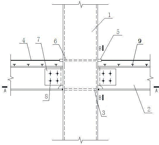
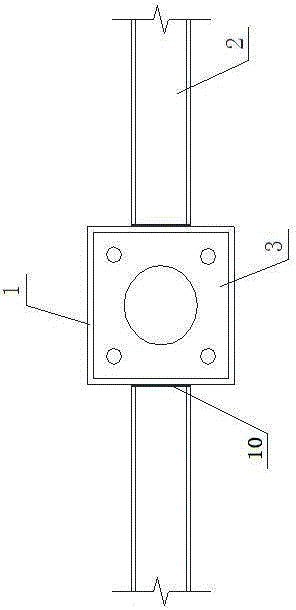
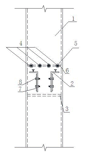
[0052] A connection node between a concrete-filled steel tube column and an outer U-shaped steel-concrete composite beam. As shown in the figure, it includes an inner partition 3 and a horizontal stiffening plate 6. The inner partition 3 and the horizontal stiffening plate 6 are respectively provided with pouring holes 12 and the ventilation hole 11 ensure the smooth concrete pouring in the steel pipe 1. The inner partition 3 is located in the steel pipe 1 at the position corresponding to ...


PUM


Abstract

The invention provides a connection joint of a concrete filled steel tubular column and enclosed U-shaped steel concrete composite beam; in order to save materials and solve the problem that since a connection plate at the connection part of a composite beam bottom plate and a steel pipe outwards extends, an indoor corner has a convex angle to influence the beautiful sense, an inner partition plate is arranged at a position corresponding to a U-shaped steel bottom plate in the steel pipe, and the periphery of the inner partition plate is welded with the inner wall of the steel pipe. Sleeves which are movably connected with the end parts of hogging moment reinforcing steel bars are correspondingly arranged at two relative ends in the steel pipe along the length direction of the composite beam respectively; and the sleeves are welded with the outer wall of the steel pipe. The joint is capable of relieving the condition that the bearing capacity of the steel pipe is weakened due to hole forming in the side wall of the steel pipe; the welding workload is reduced; construction is facilitated; and assembly is realized. In order to effectively transmit a load, a horizontal stiffening plate is fixedly welded at positions corresponding to the sleeves in an inner cavity of the steel pipe, and the welding workload in field is reduced; a U-shaped steel side plate is connected with the wall of the steel pipe by adopting high-strength bolts through connection plates; the connection plates are connected with the wall of the steel pipe by angle welding; and welding is completed in a factory.

Description

technical field [0001] The invention relates to a concrete-filled steel pipe column and an outsourcing U-shaped steel-concrete composite beam, in particular to a connection node between a steel-pipe concrete column and an outsourcing U-shaped steel-concrete composite beam. Background technique [0002] Concrete-filled steel pipe column refers to the vertical member formed by filling concrete in the steel pipe. It has the advantages of high bearing capacity, good plasticity and ductility, high rigidity, convenient construction, and good fire resistance. It has received extensive attention from the engineering community in recent years. It is used more and more in multi-high-rise buildings and bridge engineering. According to different cross-sectional forms, CFST columns can be divided into circular CFST columns, rectangular CFST columns and polygonal CFST columns. Outer U-shaped steel-concrete composite beam is directly welded or cold-bent the steel plate into U-shaped steel...

Claims


Application Information

Patent Timeline
IPC IPC(8): E04B1/30E04B1/58
Inventor 林彦周学军姜伟
Owner SHANDONG JIANZHU UNIV
Why Eureka
Try Eureka