Unlocking mechanical device

A mechanical device and door lock technology, applied in non-mechanical transmission-operated locks, building locks, buildings, etc., can solve the problems of lock shape limitation, keys are easy to lose property, passwords are easy to leak, etc., and achieve stable rotation, labor-saving and convenient. The effect of unified management and solving management problems

Inactive Publication Date: 2015-09-16
CHENGDU YUFEI TECH
View PDF7 Cites 3 Cited by
  • Summary
  • Abstract
  • Description
  • Claims
  • Application Information

AI Technical Summary

Problems solved by technology

The existing unlocking methods mainly adopt mechanical key unlocking, fingerprint unlocking, password unlocking, credit card unlocking and mobile phone unlocking. Once the simple mechanical key is lost, it will cause great inconvenience to people; the way of password unlocking will cause the shape of the lock to be affected. Restricted and pressing the same password for a long time will cause the keyboard change password to be easily leaked; swiping the card to unlock the lock has the same security problem as the key
[0003] In addition, in a certain period of time, it is necessary to temporarily and frequently allow irregular people to enter and exit. At this time, the security risks brought about by the usual unlocking method are more obvious.
For example, when a house is being renovated, different types of workers and material suppliers need to enter the site, key management is prone to handover difficulties, and keys are easy to lose and cause property damage. If you can use remote control to open the door on site, you can achieve keyless Orderly management can solve these problems to some extent
[0004] However, the existing non-contact or remote unlocking devices require a substantial modification of the original locks, so the cost and benefit ratio is very prominent

Method used


Image

  • Unlocking mechanical device
  • Unlocking mechanical device
  • Unlocking mechanical device

Examples


Embodiment

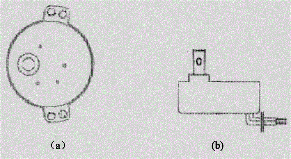
[0031] The main components of the device include: a motor, a fixed base plate, a swing arm, a steel wire rope for connection, a U-groove transmission roller and a handle fixture.

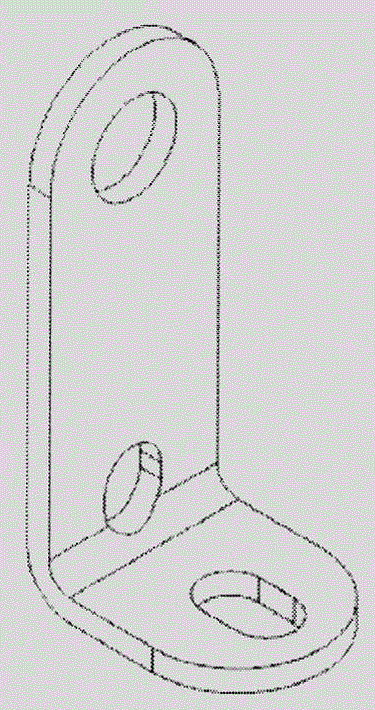
[0032] Such as Figure 4 As shown, the fixed bottom plate is cut from a 1.5mm stainless steel plate and made into an irregular shape approximately elongated. The upper fork 10 and the lower connecting hole 11 of the bottom plate are the fixing mechanism for the door lock. 11 corresponds to the upper and lower two fixed screw hole positions of the door lock respectively.

[0033] Such as figure 2 As shown, the motor 1 adopts TYD49 non-directional claw pole permanent magnet synchronous motor. The top end of the shaft has an M4 internal thread, and the middle section of the shaft has a hole with a diameter of 3 mm to fix the swing arm. Such as Figure 5 with 6 As shown, the motor uses two m4*25 screws 8 to pass through the two furthest holes on the motor ears respectively, and pass down through th...


PUM


Abstract

The invention relates to an unlocking mechanical device, in particular to a device used for controlling and simulating opening of a door by manual labor in a contactless mode. The technical scheme adopted by the unlocking mechanical device is characterized in that a rotary oscillating arm is arranged on a motor shaft; an oscillating end of the rotary oscillating arm is connected with a handle clamp by means of a drag wire; a motor is controlled by cooperation with a relay; and in the way that axial motion of the motor is converted to up-down reciprocating motion, door-opening actions of a hand in the door can be simulated so that the door can be opened inside without a key by a contactless mode or a remote control module when no person exists inside the door. The unlocking mechanical device has following beneficial effects: by replacing a conventional mode of utilizing the key to unlock, the unlocking mechanical device is used for a special period of time in need of a temporary frequent permit allowing any person to go in and out; due to a simple structure, low production cost and a remote unlocking function, safety is improved and a solution for unified management of unlocking is provided; and the unlocking mechanical device is of great promotional value.

Description

technical field [0001] The invention relates to a lock unlocking mechanism, more particularly to a device for simulating manual opening of a door lock through non-contact manipulation. Background technique [0002] With the rapid development of society and more instability in the development process, people pay more attention to safety issues, and the safety of home door locks is usually very important. The existing unlocking methods mainly adopt mechanical key unlocking, fingerprint unlocking, password unlocking, credit card unlocking and mobile phone unlocking. Once the simple mechanical key is lost, it will cause great inconvenience to people; the way of password unlocking will cause the shape of the lock to be affected. Restricting and pressing the same password for a long time will cause the keyboard change password to be easily leaked; swiping the card to unlock the lock has the same security problems as the key. [0003] In addition, in a certain period of time, it i...

Claims


Application Information

Patent Timeline
IPC IPC(8): E05B47/00
Inventor 石东华
Owner CHENGDU YUFEI TECH
Why Eureka
Try Eureka