Fluid dynamic machine with rotating wheel and rotary vane synchrocyclotron mechanism

A technology of fluid power and runners, which is applied in the direction of machines/engines, rotary piston machines, mechanical equipment, etc., and can solve problems such as low efficiency, reciprocating friction and wear, and poor sealing performance

Pending Publication Date: 2015-09-16
南通金鼎天轮动力科技有限公司
View PDF1 Cites 7 Cited by
  • Summary
  • Abstract
  • Description
  • Claims
  • Application Information

AI Technical Summary

Problems solved by technology

[0002] The current volumetric fluid power machinery has many defects such as complex structure, low efficiency, reciprocating friction and wear, and poor sealing performance. Movement Mechanism of Existing Fluid Power Machinery
I applied for an invention patent on December 16, 2014. The patent name: Fluid power machinery with a rotary blade rotary mechanism. The application number: 201410771322.6. This technology only has rotational motion without reciprocating frictional motion, but there are still complex structures , poor motion stability and other defects, need to take further improvement measures

Method used


Image

  • Fluid dynamic machine with rotating wheel and rotary vane synchrocyclotron mechanism
  • Fluid dynamic machine with rotating wheel and rotary vane synchrocyclotron mechanism
  • Fluid dynamic machine with rotating wheel and rotary vane synchrocyclotron mechanism

Examples


Embodiment Construction

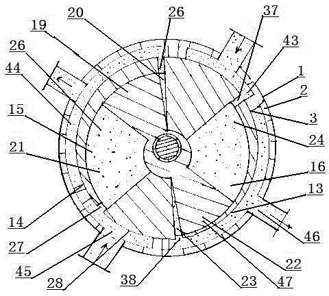
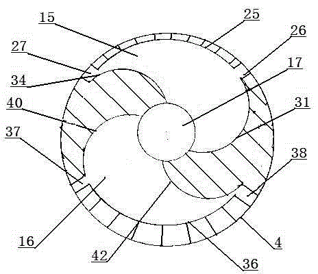
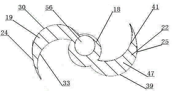
[0028] like figure 1 , figure 2 , image 3 As shown, the runner and rotary vane synchronous turning mechanism 1 is composed of a body 2 , a cylinder head 6 , a cylinder liner 3 , a runner 4 , a transmission shaft 7 , a rotary impeller 5 and a runner cycloid mechanism 11 . like Figure 5 As shown, one end of the transmission shaft 7 is supported and installed in the bearing seat 8 of the body 2 , and the lower wall surface 9 of the runner 4 is concentrically and fixedly connected with the transmission shaft 7 . like Image 6 As shown, the two ends of the runner 4 are supported and rotated by bearings, and the hollow shaft 57 fixed on the upper wall 10 of the runner 4 is supported and installed in the bearing seat 12 inside the cylinder head 6 . like figure 1 , Figure 4As shown, the runner 4 is concentrically installed in the cylinder liner 3, the outer wall 13 of the runner 4 and the inner wall 14 of the cylinder liner 3 are rotated and meshed with a dynamic seal, and t...


PUM


Abstract

The invention relates to a fluid dynamic machine with a rotating wheel and rotary vane synchrocyclotron mechanism. The fluid dynamic machine comprises a machine body (2), a cylinder cover (6), a cylinder sleeve (3), a rotating wheel (4), a transmission shaft (7), a rotary vane wheel (5) and a rotating wheel cycloid mechanism (11). A left cylinder chamber (15) and a right cylinder chamber (16) are symmetrically distributed in the rotating wheel (4), the left cylinder chamber (15) is divided into a first volume chamber (20) and a second volume chamber (21) by a left rotary vane (19) on the rotary vane wheel (5), the right cylinder chamber (16) is divided into a third volume chamber (23) and a fourth volume chamber (24) by a right rotary vane (22) on the rotary vane wheel (5), the rotary vane wheel (5) and the rotating wheel (4) are synchronously rotated under the effect of the rotating wheel cycloid mechanism (11), the rotating wheel (4) are rotated for one circle, and suction and discharge work by eight times of a fluid (32) are carried out.

Description

technical field [0001] The invention relates to a synchronous rotating mechanism of a runner and rotor blades for fluid power machinery, and relates to the technical field of fluid power machinery manufacturing such as fans, pumps, hydraulic motors, compressors, expansion power machines and engines. Background technique [0002] The current positive displacement fluid power machinery has many defects such as complex structure, low efficiency, reciprocating friction and wear and poor sealing performance. The kinematic mechanism of the existing fluid power machinery. I applied for an invention patent on December 16, 2014, the patent name: Fluid Power Machinery with Rotary Vane Swirl Mechanism, Application No.: 201410771322.6, this technology only has rotary motion without reciprocating friction motion, but there are still complex structures. , poor motion stability and other defects, need to take further improvement measures. SUMMARY OF THE INVENTION [0003] The purpose...

Claims


Application Information

Patent Timeline
IPC IPC(8): F01C1/22F01C21/08F02B53/00F02B55/02F03C2/22F04C2/22F04C18/22
CPCF01C1/22F01C21/08F02B53/00F02B55/02F03C2/22F04C2/22F04C18/22Y02T10/12
Inventor 周觉明
Owner 南通金鼎天轮动力科技有限公司
Why Eureka
Try Eureka