Adaptive fault detection method for airplane rotation actuator driving device based on deep learning

A technology of rotary actuators and driving devices, which is applied in the direction of instruments, electrical testing/monitoring, testing/monitoring control systems, etc., to achieve the effect of increasing the number of layers, improving accuracy, and improving generalization ability

Inactive Publication Date: 2015-09-16
BEIHANG UNIV
5 Cites 51 Cited by

AI-Extracted Technical Summary

Problems solved by technology

[0006] The technology of the present invention solves the problem: in order to overcome the influence of system nonlinear factors on the fault detection method based on the observer, combined with the advantages of deep learning and efficient complex nonlinear function fitting and approximation, a deep learning-based aircraft rotary actuator drive is proposed The device adaptive fault detection method minimizes the influence of nonlinear factors on the residua...

Method used

(3) GRA rotary actuator adopts the principle of planetary gear transmission, has the characteristics of small volume and light weight, and can realize very high torque output in limited space, in aircraft rotary actuator (comprising hatch cover , weapons compartment, etc.) drive systems and other fields have a wide range of applications.
Noise reduction autoencoder (SDA) algorithm model is exactly based on the improved algorithm of traditional stacked autoencoder (SAE), has similarity in the training logic and construction process of neural network, is a multilayer sparse autoencoder In a deep learning neural network composed of neural networks, the output of the previous layer of autoencoder is used as the input of the next layer of autoencoder. SDA preprocesses the input samples of each layer of the entire network, so that the input data is "occluded" to a certain extent, thereby effectively improving the robustness of fault diagnosis.
[0061] Dropout technology is a method for introducing the difference of the base learner of the model layer operation. It introduces random factors to the hidden layer network nodes of the sparse autoencoder, thereby realizin...

Abstract

The invention discloses an adaptive fault detection method for an airplane rotation actuator driving device based on deep learning. According to the invention, adaptive fault detection is carried out on the airplane rotation actuator driving device based on a sparse Dropout automatic coder and a noise reduction automatic coder and deep learning of Logistic regression, feature self-learning of original data is realized through using the Dropout automatic coder in a first layer and a layered noise reduction automatic coder model in a second layer and a third layer by adopting a multi-layer neural network based deep learning autonomous cognitive method, data features acquired by learning are inputted to a Logistic regression model so as to judge an operating state of the rotation actuator driving device, a threshold is enabled to change along with different inputs and different states of the system through additionally arranging an adaptive threshold fault observer, and a residual error caused by non faults is eliminated. The method disclosed by the invention can be effectively applied to fault diagnosis of the airplane rotation actuator driving device.

Application Domain

Electric testing/monitoring

Technology Topic

Work statusAirplane +7

Image

  • Adaptive fault detection method for airplane rotation actuator driving device based on deep learning
  • Adaptive fault detection method for airplane rotation actuator driving device based on deep learning
  • Adaptive fault detection method for airplane rotation actuator driving device based on deep learning

Examples

  • Experimental program(1)

Example Embodiment

[0049] The present invention will be described in detail below in conjunction with the drawings and embodiments.
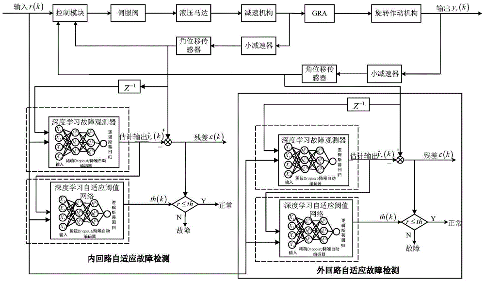
[0050] The invention discloses an adaptive fault detection method of an aircraft rotary actuator drive device based on deep learning. The method is based on the deep learning of sparse Dropout autoencoder and stacked denoising autoencoder (Stacked Denoising Autoencoder) and Logistic regression. Self-adaptive fault detection of aircraft rotary actuator driving device. Based on the failure analysis of the driving device of the aircraft rotary actuator, and in view of the current classification algorithm robustness and accuracy limitations, this method draws on the knowledge of image pattern recognition and adopts deep learning autonomous recognition based on multi-layer neural network. The well-known method uses the sparse Dropout autoencoder in the first layer and the layered noise reduction autoencoder model of the second and third layers to realize the self-expression of the original data under the condition of partial occlusion of the input, and input the reconstructed data to Logistic The regression model judges the working status of the rotary actuator drive device. By adding an adaptive threshold fault observer, the threshold changes with the different inputs of the system and the different states of the system, eliminating residual errors caused by non-faults. The test result analysis shows that the present invention can be effectively applied to the fault diagnosis of the driving device of the rotary actuator of the aircraft, and the fault detection is carried out for the different degree of failure of the driving device of the rotary actuator.
[0051] 1. Such as figure 1 Shown, the structure of the aircraft rotary actuator drive device.
[0052] The aircraft rotary actuator driving device is composed of a control module, a driving module, a servo valve, a hydraulic motor, a reduction mechanism, a GRA rotary actuator and an angular displacement sensor. The functions of each component are as follows:
[0053] (1) The control module is a module for the drive system of the rotary actuator to send instructions and receive instructions from the angular displacement sensor. The drive system of the rotary actuator is directly connected to the drive module and the SOV module through the control module. The control module sends instructions according to the feedback information of the angular displacement sensor and the signal of the micro switch. When the mechanism rotates to the specified angle, the control module sends instructions to the SOV, and the function switching valve turns to the hydraulic brake module.
[0054] (2) The drive module converts the voltage signal of the control signal into the servo valve input current signal. The main component of the drive module is the amplifier. The function of the drive module is to convert the control voltage signal of the control module into the current signal input by the electro-hydraulic servo valve, and at the same time, gain the current signal. The principle of converting voltage into current is related to its internal structure and model.
[0055] (3) The GRA rotary actuator adopts the principle of planetary gear transmission, and has the characteristics of small size and light weight. It can achieve a high torque output in a limited space. It can be used in aircraft rotating actuators (including hatch covers and weapon bays). Etc.) Drive systems and other fields have a wide range of applications.
[0056] (4) The direct function of the angular displacement sensor is a device that converts the output angular displacement of the aircraft rotary actuator drive device into an electrical signal. The electrical signal converted by the angular displacement sensor is fed back to the control module.
[0057] The operation of the door drive device is divided into the door opening/closing phase, and the door braking phase consists of two phases. The equipment running in the two stages is different, the operation principle diagram of the two stages is as follows figure 1 Shown. Since there is no signal from the two angular displacement sensors in the holding phase, the holding phase is not the research object.
[0058] figure 1 The middle solid line represents the door opening/closing phase command process, and the dotted line represents the feedback signal. It can be seen that when the door is opened/closed, the control module issues an instruction. After the function switching valve receives the SOV current from the control module, it performs a switching function. The drive module drives the servo valve with a current EHV, and the servo valve drives the hydraulic motor, and then drives the GRA to rotate. , The rotary actuator is turned on/off. When the rotary actuator is opened to a certain angle and needs to be braked, an RVDT sensor at the end of the GRA gives a feedback voltage to the control module to feedback the angle of the GRA. The control module cuts off the command to the drive module, drives the function switching valve, and switches the oil circuit. The hydraulic brake is driven to brake the hydraulic motor to achieve the state of braking/holding.
[0059] 2. Deep learning regression technology based on the combination of sparse Dropout autoencoder and noise reduction autoencoder
[0060] (1) Sparse Dropout autoencoder technology
[0061] Dropout technology is a differentiated introduction method of the base learner for model layer operations. It introduces random factors to the hidden layer network nodes of the sparse autoencoder, thereby achieving model averaging and improving the generalization ability of the network. In the case of fewer training samples or complex sample composition, when training deep learning neural network models, in order to prevent the model from overfitting and improve the generalization ability of the model, Dropout is an effective method. When the deep learning network model is trained, it randomly makes the weights of some hidden layer nodes in the network not work with a certain distribution probability (for example: according to a uniform distribution, for each input sample, randomly select 50% of the hidden layer node weights. Working), these non-working nodes can be temporarily considered as not part of the network structure, but their weights are temporarily stored (just this time the sample input, the corresponding weights of these nodes will not be updated temporarily), so that the next sample input Use when it may work.
[0062] The specific implementation of Dropout technology is as follows:
[0063] Dropout refers to making certain hidden layer units in the neural network inoperative, and making it inoperative refers to the ability to remove these hidden layer units, together with their input and output connection weights, from the neural network. The choice of removing hidden layer units is random. Taking the simplest case as an example, each hidden layer unit is retained with a certain fixed probability p, and the value of p depends on the specific task problem solved by the neural network and the input data Features. Dropout technology is independently applied to each hidden layer unit or training input sample. By applying Dropout technology, it is similar to randomly "sub-sampling" a large neural network to obtain a set of sub-neural networks. A neural network with n hidden layer units can be regarded as a neural network with 2n possible sub-neural networks. These sub-networks share weights so that the total number of network parameters is still O(n 2 ), or even less.
[0064] The dropout neural network model is described as follows. Assuming a neural network with L hidden layer units, let l∈{1,2,...,L} denote different hidden layers of the neural network. z (l) Represents the input of the lth hidden layer, y (l) Represents the output of the lth hidden layer (y (0) = X is input). W (l) And b (l) They are the weight and bias of the first layer.
[0065] The feedforward operation of ordinary neural networks can be described as (for l∈{1,2,...,L-1}).
[0066] z (l+1) =W (l+1) y l +b (l+1) (1)
[0067] y (l+1) =f(z (l+1) ) (2)
[0068] Among them, f is an arbitrary activation function.
[0069] After applying Dropout technology, the formula for feedforward operation becomes:
[0070] r i (l) ~ Bernoulli(p) (3)
[0071] y ~ = r ( l ) * y ( l ) - - - ( 4 )
[0072] z ( l + 1 ) = W ( l + 1 ) y ~ l + b ( l + 1 ) - - - ( 5 )
[0073] y (l+1) =f(z (l+1) ) (6)
[0074] Where r (l) Is a vector composed of Bernoulli random variables. The probability that the Bernoulli random variable takes a value of 1 is p. This vector is sampled separately for each hidden layer and is compared with the output y of the hidden layer (l) Multiply to generate the output of the sub-network using Dropout technology The output of the sub-network is used as the input of the next hidden layer of the network. In the learning and training process, the deviation of the loss function is back propagated through the sub-network. During the test, the weights are changed according to the following proportions to form a "mean network", that is, model averaging, to obtain the output of the hidden layer, which is actually the hidden layer node before the network is propagated forward to the output layer The output value must be halved.
[0075] (2) Noise reduction automatic encoder technology
[0076] The denoising autoencoder (SDA) algorithm model is an improved algorithm based on the traditional stacked autoencoder (SAE). It has similarities in the training logic and construction process of the neural network. It is composed of a multi-layer sparse autoencoder. In the deep learning neural network, the output of the previous layer of autoencoder is used as the input of the next layer of autoencoder. SDA preprocesses the input samples of each layer of the entire network, so that the input data is "shielded" to a certain extent, thereby effectively improving the robustness of fault diagnosis.
[0077] In terms of the setting of network parameters, the initialization of the SDA model neural network parameters adopts a layer-by-layer greedy training method, that is, the first layer of the network is trained using the original input to obtain the weights and bias parameters; then the first layer of the network combines the original The input is transformed into a vector composed of the activation values ​​of the hidden unit (assuming that the vector is A). At this time, A is the first-order feature representation of the original data, that is, the lowest expression method; then A is used as the input of the second layer to continue training Obtain the parameters of the second layer. The parameters of this layer are second-order features reconstructed from the first-order features, which is a more abstract expression method; finally, the same strategy is adopted for the subsequent layers, that is, the output of the previous layer is used as the next The input method of the layers is trained sequentially, and the parameters of the other layers are fixed to remain unchanged when the parameters of each layer are trained. The present invention inputs the output of the last hidden layer as a feature to the Logistic regression classifier for classification, so that the gradient value of the classification error of the classifier is directly backpropagated to the coding layer.
[0078] (21) "Occlusion" preprocessing based on uniform distribution of input samples
[0079] The present invention uses a random mapping method to set the value of some nodes in the input sample to 0, and obtain a new, partially occluded sample The specific occlusion process is: set an expected occlusion probability as υ, randomly select υd number of input nodes, force their node values ​​to 0, and keep other node values ​​unchanged. Therefore, the original information of all selected nodes is removed from the input samples, and the trained autoencoder needs to learn these "lost" information, so that the reconstructed data is also in the absence of information. It can express the original data well, that is, when the test sample and the training sample do not conform to the same distribution or have a large difference, good results can also be achieved. Assume that the joint distribution function is:
[0080] q 0 ( x , x ~ , y ) = q 0 ( x ) qD ( x ~ | x ) δ f θ ( x ~ ) ( y ) - - - ( 7 )
[0081] When μ≠υ, change δ μ (υ) Set to 0 to realize the data occlusion process. Y is the determined sigmod mapping function between the input layer and the hidden layer, so It is determined by the parameter θ.
[0082] (22) Original data reconstruction based on SDA
[0083] The SDA model training process adopts a layer-by-layer training method. First, a occluded input sample is given By training the first hidden layer, the expression h1 of the original sample data x is obtained, and then the output h1 of the first hidden layer is subjected to the same occlusion processing, and the second hidden layer is trained. Learn the expression h2 of h1...that is, first use the "destroyed" original input to train the first layer of the network, and use the same strategy for the subsequent layers, occlude the output of the previous layer as the input of the next layer , The output result z of the final layer is the expression of the reconstructed original data x. Unlike traditional stacked autoencoders, z reconstructed by SDA is the original data x expressed, not the input samples after occlusion
[0084] The training of the SDA model has two steps: unsupervised self-learning and supervised fine-tuning. In order to more effectively find the structure and pattern hidden in the input data, we use sparse coding to perform unsupervised self-learning of the original data features:
[0085] (A) Sparse expression of original data features
[0086] This method uses the concept of basis vector in linear algebra to express the output data, O=α 1 Φ 1 +α 2 Φ 2 +...α n Φ n , Φ n Is the base, α n Is a coefficient. In order to better express the original data, there is an optimization condition Min|I-O|, where I represents input and O represents output.
[0087] By solving this optimization formula, the coefficient α can be obtained n And base Φ n , These coefficients and basis are another approximate expression of the input.
[0088] x = X i = 1 k α i φ i - - - ( 8 )
[0089] In the above formula with L 1 Normal form cost function S(a i )=|a i | 1 With sparse restriction, the sparse coding cost function of m input vectors can be obtained, which is defined as:
[0090] min imize a i ( j ) , φ i X j = 1 m | | x ( j ) - X i = 1 k a i ( j ) φ i | | 2 + λ X i = 1 k S ( a i j ) - - - ( 9 )
[0091] Using sparse coding can represent a signal as a linear combination of a set of bases, and requires only a few bases to represent the signal. "Sparseness" is defined as: there are only a few non-zero elements or only a few elements far greater than zero, that is, for a set of input vectors, only as few coefficients as possible are far greater than zero.
[0092] The sparse coding process is divided into two parts:
[0093] Training phase: Given a series of sample data [x 1 ,x 2 …], learn a set of basis [Φ 1 ,Φ 2 ,...].
[0094] Sparse coding is a variant of the k-means algorithm. Its training process is a process of repeated iterations, which minimizes the objective function by alternately changing a and Φ.
[0095] min a , φ X i = 1 m | | x i - X j = 1 k a i , j φ j | | 2 + λ X i = 1 m X j = 1 k | a i , j | - - - ( 10 )
[0096] Each iteration is divided into two steps:
[0097] a) Fix the basis vector Φ[k], and then adjust the weight a[k] to minimize the objective function.
[0098] b) Then fix the weight a[k] and adjust the basis vector Φ[k] to minimize the objective function.
[0099] By continuously iterating to convergence, a set of basis representing this series of x can be obtained.
[0100] Coding stage: Given a set of new input samples x, from the basis vector Φ[k] obtained above, the sparse vector a is obtained by solving a LASSO regression problem. This sparse vector is a sparse expression of the new x.
[0101] min a X i = 1 m | | x i - X j = 1 k a i , j φ j | | 2 + λ X i = 1 m X j = 1 k | a i , j | - - - ( 11 )
[0102] (B) Initialize the weights and bias parameters of the network randomly, and perform forward unsupervised self-learning.
[0103] After determining the sparse expression rules, this method takes a single-layer neural network as an example, assuming that the mapping function between the input layer of the neural network and the hidden layer is:
[0104] y = f θ ( x ~ ) = s ( W x ~ + b ) , θ = { W , b } - - - ( 12 )
[0105] Where W is a d'×d weight matrix, and b is the bias vector.
[0106] At the same time, the output y of the hidden layer can be reversed to reconstruct a vector z∈[0,1] d , The mapping function is:
[0107] z=g θ′ (y)=s(W′y+b′),θ′={W′,b′} (13)
[0108] The weight matrix W′ can be expressed as W′=W T.
[0109] Therefore, x (i) Can output y through the hidden layer (i) Reconstruct a new expression z (i). In order to obtain the best reconstruction characterization z, the model parameters can be optimized by minimizing the variance cost function.
[0110] Define a single variance cost function as:
[0111] J ( W , b ; x , y ) = 1 2 | | h W , b ( x ) - y | | 2 - - - ( 14 )
[0112] The overall cost function can be obtained:
[0113] J ( W , b ) = [ 1 m 1 X i = 1 m J ( W , b ; x ( i ) , y ( i ) ) ] + λ 2 X l = 1 n i = 1 X i = 1 s l X j = 1 s l + 1 ( W ji ( l ) ) 2 = [ 1 m X i = 1 m ( 1 2 | | h W , b ( x ( i ) ) - y ( i ) | | 2 ) ] + λ 2 X l = 1 n i - 1 X i = 1 s l X j = 1 s l + 1 ( W ji ( l ) ) 2 - - - ( 15 )
[0114] In the process of forward propagation, the weight And bias It is initialized to a small random value close to zero, and then the objective function is optimized using batch gradient descent.
[0115] (3) Logistic regression
[0116] Linear regression model is a very popular statistical analysis method in the actual research of quantitative analysis. However, in many cases, linear regression will be limited, or sometimes a nonlinear regression model or other models are more appropriate based on experience or theory. In the nonlinear regression model, the Logistic regression model used when the response variable is a categorical variable, especially a binary variable, is a very promising model.
[0117] Logistic regression is a multivariate statistical method, which is suitable for the case where the response variable is a binary (normal and abnormal) variable. The independent variable can be a categorical variable or a continuous variable. The goal is to model the probability of the response variable taking one of two values, rather than directly predicting its value. There is an S-shaped curve relationship between the probability of abnormal value of the independent variable and the response variable. For any argument X k Under the condition that other independent variables remain unchanged, with the increase of the value, the probability P increases very slowly at first, then accelerates, and finally stabilizes again, but never exceeds 1.
[0118] Suppose there is a theoretically existing link response variable Represents the possibility of an event, and its range is from negative infinity to positive infinity. When the value of the variable crosses a critical point c (for example, c=0), an event occurs. So there are:
[0119] when When, y i =1;
[0120] In other cases, y i =0.
[0121] Here, y i Is the actual observed response variable, y i =1 means the event occurred, y i =0 means that the event did not occur. If the assumption is in response to the variable And the independent variable x i There is a linear relationship between
[0122] y i * = α + β x i + ϵ i - - - ( 16 )
[0123] Obtained by formula (16):
[0124] P(y i =1|x i )=P[(α+βx i +ε i )> 0]=P[ε i (-α-βx i )] (17)
[0125] Assume that the error term ε in formula (17) i For Logistic distribution, there are:
[0126] P ( y i = 1 | x i ) = P [ ϵ i ≤ ( α + β x i ) ] = 1 1 + e - ϵ i - - - ( 18 )
[0127] This function is called the Logistic function, and it has an S-shaped distribution.
[0128] In order to switch from Logistic function to Logistic regression model, formula (18) is rewritten as:
[0129] P ( y i = 1 | x i ) = 1 1 + e - ( α + β x i ) - - - ( 19 )
[0130] Label the conditional probability of an event as P(y i =1|x i )=p i , We get the Logistic regression model:
[0131] p i = 1 1 + e - ( α + β x i ) = e α + β x i 1 + e α + β x i - - - ( 20 )
[0132] Where p i Is the probability of occurrence of the i-th case, which is an explanatory variable x i Non-linear function formed. But it can be transformed into a linear function.
[0133] First, define the conditional probability of no event as:
[0134] 1 - p i = 1 - ( e α + β x i 1 + e α + β x i ) = 1 1 + e α + β x i - - - ( twenty one )
[0135] Then the ratio of the probability of occurrence of an event to the probability of not occurring is:
[0136] p i 1 - p i = e α + β x i - - - ( twenty two )
[0137] This ratio becomes the occurrence ratio of the event, which is a positive value and has no upper bound. Taking the natural logarithm of the occurrence ratio, a linear function can be obtained:
[0138] ln ( p i 1 - p i ) = α + β x i - - - ( twenty three )
[0139] Equation (23) regards the Logistic function as a natural logarithmic transformation, which is called the logit form, which is also called the logit transformation of y, namely Logit(y).
[0140] There are k independent variables, and formula (20) is expanded to:
[0141] p i = e α + X k = 1 k β k x ki 1 + e α + X k = 1 k β k x ki - - - ( twenty four )
[0142] Then, the corresponding Logistic regression model form is as follows:
[0143] ln ( p i 1 - p i ) = α + X k = 1 k β k x ki - - - ( 25 )
[0144] Where p i =P(y i =1|x 1i ,x 2i ,...X ki ) Is the independent variable x in the given series 1i ,x 2i ,...X ki The probability of occurrence of the event at the value.
[0145] Once we have the observed independent variable x for each case 1 To x k The present invention can use this information to analyze and express the probability of occurrence of the event under specific conditions.
[0146] (4) Adaptive fault detection technology of control system based on deep learning regression
[0147] The control system fault detection method based on the deep learning network regressor, the observer constructed by the deep learning regressor is used to generate residual information, and the deep learning regressor is used to establish an adaptive threshold network to generate an adaptive threshold to realize an adaptive judgment control system Whether there is a failure. The following describes the observer and adaptive threshold construction methods based on deep learning regression.
[0148] (41) Basic principle of fault observer
[0149] Suppose the system with faults is described by equation (26):
[0150] X ( t ) = g ( t , X , U , Y , F ) Y ( t ) = h ( t , X , U , Y , F ) - - - ( 26 )
[0151] In the formula, X(t), Y(t), U(t), F(t) respectively represent the state vector, measured output vector, control input vector and fault vector of the system, and g and h are nonlinear vector functions.
[0152] Define the state observer as:
[0153] X ^ ( t ) = g ( t , X ^ , U , Y , F ^ ) Y ^ ( t ) = h ( t , X ^ , U , Y , F ^ ) - - - ( 27 )
[0154] Where These are the estimated values ​​of X(t), Y(t), and F(t).
[0155] Let the observation error:
[0156] E ( t ) = X ( t ) - X ^ ( t ) - - - ( 28 )
[0157] If for F(t)=0 and F(t)≠0, both If yes, the state observer (27) is called the fault observer of the system (26).
[0158] Based on the above nonlinear system, the output residual of the state observer is The fault detection can be achieved through appropriate logic, such as through the threshold judgment principle. The threshold here can be obtained based on actual data, or a fixed threshold can be set based on expert experience, but this article will adopt an adaptive threshold for fault detection.
[0159] (42) Construction of control system fault observer based on deep learning regression
[0160] Combine the traditional observer with the deep learning regressor to get figure 2 Shown is a schematic diagram of the structure of a two-stage fault observer based on a deep learning regression. The deep learning observer adopts a deep learning regression based on sparse Dropout autoencoder, noise reduction autoencoder and logistic regression.
[0161] Deep learning regression input layer: The input of the network is the system control instruction r(k) and the system output signal y r (k); The first and second layers are sparse Dropout autoencoders or noise reduction autoencoders; the third layer is the output layer using logistic regression algorithm: the output of the network is the estimated output signal of the system The determination of network parameters includes the weight W between the input layer, the hidden layer and the output layer.
[0162] When the deep learning fault observer is trained, the training input samples used are the input command r(k) of the system and the output signal y of the system r (k), the training output sample is the output signal of the system Collect a large number of samples to train the fault observer based on the deep learning regression to determine the structural parameters of the deep neural network and logistic regression. At this time, please pay attention: the training fault observer should contain as much data information as possible. Assume the residual error ε(k) of the control system:
[0163] ϵ ( k ) = y r ( k ) - y ^ r ( k ) .
[0164] When the deep learning fault observer is trained with data samples in the normal state of the control system, the structural parameters of the deep learning neural network can be determined, that is, the weight W between the input layer, hidden layer and output layer is determined And stay the same. These determined structural parameters are equivalent to memorizing the state of the system when it is normal. Under normal circumstances, the estimated output of the deep learning fault observer is not much different from the true output of the system, and generally fluctuates around zero. This is due to the interference of the system And other factors.
[0165] When performing fault detection in the control system, the input and output signals of the current system are used as the detected sample input of the trained deep learning fault observer, and the estimated output of the observer is compared with the output signal of the system to obtain the current system state Residual.
[0166] (43) Construction method of adaptive threshold for control system fault detection based on deep learning regression
[0167] There is an error between the real system and the model. Under different input instructions and different system states, the output produced is different, so the required threshold should also change with the different inputs of the system and the different states of the system. The residual error caused by non-fault, the threshold that changes with the working state of the system, is the adaptive threshold. Adaptive threshold is the key content of threshold research. Current research mainly focuses on three aspects: based on analytical models, based on fuzzy theory, and based on random signal processing. At present, adaptive threshold research has gradually begun to use shallow neural networks. Research on adaptive thresholds using deep neural networks has not been carried out yet.
[0168] There are many factors that affect the threshold, so the following factors need to be considered when selecting the threshold:
[0169] (A) Modeling error:
[0170] ε(s)=[G s (s)-G m (s))×X(s) (29)
[0171] Among them, ε(s)-Laplace transform of threshold; G s (s)—Subsystem transfer function; G m (s)—The transfer function of the subsystem corresponding to the model; X(s)—The Laplace transform of the subsystem input.
[0172] (B) Error caused by the influence of interference on subsystem parameters:
[0173] ε(s)=[[G s (d))(s-G m (s)))×X(s) (30)
[0174] Among them, d—represents interference; [G s (d)](s)—The transfer function obtained by Laplace transform after the subsystem parameters are disturbed.
[0175] (C) Error caused by component parameter drift:
[0176] ε(s)=[[G s (d,△(t)))(s)-G m (s))×X(s) (31)
[0177] Where [G s (d,△(t))](s)—The transfer function obtained by Laplace transform after the subsystem parameters are disturbed and the parameters drifted; △(t)—the vector composed of the drifting parameters.
[0178] (D) Errors generated after the input and output (state) of the system are disturbed:
[0179] [X(d)](s)—represents the Laplace transform after the system input is disturbed;
[0180] [Y(d)](s)—represents the Laplace transform after the system output is disturbed.
[0181] The formula (31) becomes:
[0182] ε(s)=[[G s (d,△(t)))(s)-G m (s)]×[X(d)](s) (32)
[0183] Among them [Y(d)](s) is implicit in the differential term of formula (16).
[0184] From the previous analysis, it can be seen that the threshold should be related to various factors such as modeling error, system input, system output, interference, and time-drifting parameters, and the influence of these factors on the adaptive threshold is a very complicated functional relationship. , So formula (32) is abstracted and expressed as a function mapping relationship:
[0185] ε(s)=F(d,△(t),X(s),Y(s)) (33)
[0186] Among them, F-represents the mapping function from various influencing factors to the threshold in the frequency domain.
[0187] In the actual calculation of the threshold, because interference and system parameter drift are difficult to measure, the usual method is to ignore these effects and calculate the threshold before making appropriate corrections:
[0188] ε(s)=F(X(s),Y(s)) (34)
[0189] When the control system fails, the output of the system will be unknown. At this time, the adaptive threshold should not be calculated, because the adaptive threshold has nothing to do with the failure of the system; because the deep learning normal observer of the control system has been established before Model, and the output of the model is very close to the output of the normal system, so the output of the model Y m (s) Calculate the adaptive threshold instead of the output of the system.
[0190] Therefore, the formula (34) is actually:
[0191] ε(s)=F(X(s),Y m (s)) (35)
[0192] Where Y m (s)—Indicates the output of the identification model.
[0193] For simplicity, Y(s) is still used instead of Y in the formula m (s), Y is actually used m (s).
[0194] When the control system is normal, if the input, model output, and residual sequence of the system are known, the neural network can be used to identify f and realize the calculation of the adaptive threshold.
[0195] The present invention utilizes the fitting advantage of deep learning for complex non-linear functions, and adopts deep learning regression to construct an adaptive threshold network. The method takes the input of the control system and the output result of the observer model as input, through the deep neural network regressor, through layer-by-layer feature self-learning, and comprehensive calculation to obtain an adaptive threshold. The principle of the method is as follows image 3 As shown, by inputting the estimated output of the data of the rotary actuator drive system in the first-stage observer and the control signal of the rotary actuator drive system into the deep learning adaptive threshold neural network observer, the entire rotation is obtained. The output of the adaptive threshold of the actuation mechanism drive system.
[0196] 3. The establishment of an adaptive fault detection model for the driving device of the aircraft rotary actuator based on the deep learning regression
[0197] The adaptive fault detection of the driving device of the aircraft rotary actuator is composed of two parts: the fault observer of the deep learning regressor and the adaptive threshold network of the deep learning regressor.
[0198] (1) The deep learning regression model of the aircraft rotary actuator drive device fault observer model
[0199] The deep learning regression fault observer of the aircraft rotary actuator driving device is composed of a stacked autoencoder (based on the combination of a sparse dropout autoencoder and a noise reduction autoencoder) and a logistic regression model.
[0200] The cascading autoencoder parameters are set as follows:
[0201] The first layer is a sparse dropout autoencoder, the number of input nodes is 256 (16*16), the number of hidden layer nodes is 100, the dropout probability is 0.1, the noise reduction occlusion probability is 0, the sparsity is set to 0.1, and the cost function sparsity The penalty factor is set to 3, and the cost function weight attenuation factor is set to 0.003.
[0202] The second layer is the noise reduction autoencoder, the number of input nodes is 100, which is the number of hidden layer nodes of the first layer sparse dropout autoencoder, the number of hidden layer nodes is 100, and the noise reduction occlusion probability is 0.1 (in accordance with uniform distribution) , The sparsity is set to 0.1, the cost function sparsity penalty factor is set to 3, and the cost function weight decay factor is set to 0.003.
[0203] The third layer is the noise reduction autoencoder, the number of input nodes is 100, which is the number of hidden layer nodes of the second layer noise reduction autoencoder, the number of hidden layer nodes is 100, and the noise reduction occlusion probability is 0.1 (in accordance with uniform distribution) , The sparsity is set to 0.1, the cost function sparsity penalty factor is set to 3, and the cost function weight decay factor is set to 0.003.
[0204] The parameters of the logistic regression model are set as the number of input nodes 100, which is the number of hidden layer nodes of the third-layer noise reduction autoencoder, and the number of output nodes is 1.
[0205] (2) Deep learning adaptive threshold network model of aircraft rotary actuator driving device
[0206] The deep learning adaptive threshold network of the aircraft rotary actuator driving device is composed of a stacked autoencoder (based on the combination of a sparse dropout autoencoder and a noise reduction autoencoder) and a logistic regression model.
[0207] Parameter setting of cascaded auto encoder:
[0208] The first layer is the sparse dropout autoencoder, the number of input nodes is 2, the input is the aircraft rotary actuator drive device input and the observer residual, the number of hidden layer nodes is 100, the dropout probability is 0.5, and the noise reduction occlusion probability is 0. The sparsity is set to 0.1, the cost function sparsity penalty factor is set to 3, and the cost function weight decay factor is set to 0.003.
[0209] The second layer is the noise reduction autoencoder, the number of input nodes is 100, which is the number of hidden layer nodes of the first layer sparse dropout autoencoder, the number of hidden layer nodes is 100, and the noise reduction occlusion probability is 0.1 (in accordance with uniform distribution), The sparsity is set to 0.1, the cost function sparsity penalty factor is set to 3, and the cost function weight decay factor is set to 0.003.
[0210] The parameters of the logistic regression model are set to the number of input nodes 100, which is the number of hidden layer nodes of the second layer of noise reduction autoencoder, and the number of output nodes is 1.
[0211] The present invention selects the value of the adaptive threshold through experiments, and finds that the diagnostic effect of the observer is the best when the inner loop adaptive threshold parameter is b=0.5 and the outer loop adaptive threshold parameter b=0.7. Therefore, The present invention uses these two values ​​to perform diagnosis.
[0212] 4. Case study
[0213] (1) Fault injection
[0214] In order to verify the effectiveness of the method proposed in the present invention, we established a simulation model, based on the FMECA analysis of the aircraft rotary actuator driving device, comprehensively considering the frequency of failure, the degree of damage of the failure, and the feasibility of the failure injection method. Three types of corresponding typical faults were identified and faults were injected, namely, the fault that the magnetic field strength of the servo valve decreases, the fault that the gap in the servo valve slide valve assembly increases, and the GRA output efficiency decreases. Table 2 shows the failure modes of these three faults and the specific methods of fault injection.
[0215] Table 1 Failure modes injected by the simulation model and specific fault injection methods
[0216]
[0217] (2) Self-adaptive fault detection results of the internal loop of the aircraft rotary actuator drive device
[0218] (21) Servo valve magnetic field strength reduction failure
[0219] In the established simulation model, the failure of reducing the magnetic field intensity of the servo valve is simulated by injecting the failure of the servo valve flow rate reduction into the simulation model, which is changed to 0.8, 0.6 and 0.4 times of the original flow respectively. After the fault is injected, the simulation is performed and the simulation data is obtained. The simulation data is detected by the adaptive fault detection method based on the deep learning regression proposed in this paper, and the detection result is obtained.
[0220] (A) The magnetic field strength of the servo valve is reduced. Failure degree 1
[0221] Inject the servo valve magnetic field strength reduction fault 1 into the simulation model, which is represented by the decrease of the servo valve flow rate, which is 0.8 times of the original flow rate. Figure 4 It is the test result of the circuit in the driving device of the rotary actuator. It can be seen from the figure that the observation result of the inner loop observer is that the rotary actuator device is in a fault state.
[0222] (B) The magnetic field strength of the servo valve is reduced. Failure degree 2
[0223] Inject the servo valve magnetic field strength reduction fault 2 into the simulation model, which manifests as the decrease of the servo valve flow rate, which is 0.6 times of the original flow rate. Figure 5 It is the test result of the circuit in the driving device of the rotary actuator. From Figure 5 It can be clearly seen that the observation result of the inner loop observer is that the rotating actuator device is in a fault state.
[0224] (C) The magnetic field strength of the servo valve is reduced.
[0225] Inject the servo valve magnetic field strength reduction fault 3 into the simulation model, which is represented by the decrease of the servo valve flow rate, which is 0.4 times of the original flow rate. Image 6 It is the test result of the circuit in the driving device of the rotary actuator. From Image 6 It can be clearly seen that the result of the observation of the inner loop observer is that the rotary actuator device is in a fault state.
[0226] by Figure 4 , Figure 5 with Image 6 The three servo valve magnetic field strength reduction faults can be seen. When the servo valve magnetic field reduction fault of the rotary actuator drive device is more serious, the established inner loop observer residual error exceeds the adaptive threshold more points, which also shows that The more serious the failure of the rotary actuator drive device, which proves that the inner loop fault observer can well detect the failure of the servo valve magnetic field strength reduction of the rotary actuator drive device.
[0227] (22) The internal clearance of the servo valve spool valve assembly increases fault
[0228] In the established simulation model, the failure of increasing the clearance in the servo valve spool valve assembly is simulated by injecting the failure of the flow rate reduction of the servo valve into the simulation model, which is changed to 0.9, 0.7 and 0.5 times of the original flow respectively. After the fault is injected, the simulation is performed and the simulation data is obtained. The simulation data is detected by the adaptive fault detection method based on the deep learning regression proposed in this paper, and the detection result is obtained.
[0229] (A) The internal clearance of the servo valve spool valve assembly increases. Failure degree 1
[0230] In the simulation model, the internal clearance of the servo valve spool valve assembly increases fault 1, which is manifested as a decrease in the flow rate of the servo valve, which is 0.9 times the original flow rate. Figure 7 It is the test result of the circuit in the driving device of the rotary actuator. From Figure 7 It can be seen that the observation result of the inner loop observer is that the rotating actuator device is in a fault state.
[0231] (B) The internal clearance of the servo valve spool valve assembly increases. Failure degree 2
[0232] In the simulation model, the internal clearance of the servo valve spool valve assembly increases fault 2, which is manifested as a decrease in the flow rate of the servo valve, which is 0.7 times the original flow rate. Picture 8 It is the test result of the circuit in the driving device of the rotary actuator. From Picture 8 It can be clearly seen that the result of the observation of the inner loop observer is that the rotary actuator device is in a fault state.
[0233] (C) The internal clearance of the servo valve spool valve assembly increases. Failure degree 3
[0234] In the simulation model, the internal clearance of the servo valve spool valve assembly increases, fault 3, which manifests as a decrease in the flow of the servo valve, which is 0.5 times the original flow. Picture 9 It is the test result of the circuit in the driving device of the rotary actuator. From Picture 9 It can be clearly seen that the result of the observation of the inner loop observer is that the rotary actuator device is in a fault state.
[0235] by Figure 7 , Picture 8 with Picture 9 It can be seen that the increase in the clearance of the three servo valve spool valve components can be seen. When the increase in the clearance of the servo valve spool valve assembly of the rotary actuator drive device becomes 0.9 times the original flow rate, the degree of failure is low. The number of points where the residual error of the loop observer exceeds the adaptive threshold is very small, and when the internal clearance of the servo valve spool valve assembly increases and the fault becomes more serious, the number of points where the residual error of the built-up inner loop observer exceeds the adaptive threshold is more. It also shows that the fault of the rotary actuator drive device is more serious, which proves that the internal loop fault observer can well detect the failure of the increase in the internal clearance of the servo valve slide valve assembly of the rotary actuator drive device.
[0236] (23) GRA output efficiency reduction failure
[0237] In the established simulation model, by injecting the failure of the GRA output efficiency into the simulation model, the efficiency is changed to 0.7, 0.6 and 0.5 times of the original efficiency respectively. After the fault is injected, the simulation is performed and the simulation data is obtained, and the simulation data is detected by the adaptive detection method based on deep learning proposed in the present invention, and the detection result is obtained.
[0238] (A) GRA output efficiency reduces failure degree 1
[0239] The GRA output efficiency reduction fault 1 is injected into the simulation model, which is 0.7 times the original output efficiency. Picture 10 It is the test result of the circuit in the driving device of the rotary actuator. From Picture 10 It can be seen that the observation result of the inner loop observer is that the rotating actuator device is in a fault state.
[0240] (B) GRA output efficiency reduces failure degree 2
[0241] Inject GRA output efficiency reduction fault 2 into the simulation model, which is 0.6 times the original output efficiency. Picture 11 It is the test result of the circuit in the driving device of the rotary actuator. From Picture 11 It can be clearly seen that the result of the observation of the inner loop observer is that the rotary actuator device is in a fault state.
[0242] (C) GRA output efficiency reduces failure degree 3
[0243] Inject GRA output efficiency reduction fault 3 into the simulation model, which is 0.5 times the original output efficiency. Picture 12 It is the test result of the circuit in the driving device of the rotary actuator. From Picture 12 It can be clearly seen that the result of the observation of the inner loop observer is that the rotary actuator device is in a fault state.
[0244] by Picture 10 , Picture 11 with Picture 12 Three GRA output efficiency reduction failures can be seen. When the GRA output efficiency of the rotary actuator drive device is 0.7 times the original output efficiency, the degree of failure is low, and the number of points where the residual error of the inner loop observer exceeds the adaptive threshold is few , And when the GRA output efficiency is lower, the established inner loop observer residual error exceeds the adaptive threshold more points, which also shows that the failure of the rotary actuator drive device is more serious, thus proving the inner loop fault observer The failure of the GRA output efficiency of the rotary actuator drive device can be well detected.
[0245] (3) Self-adaptive fault detection results of the outer loop of the aircraft rotary actuator drive device
[0246] (31) Servo valve magnetic field strength reduction failure
[0247] In the established simulation model, the failure of reducing the magnetic field intensity of the servo valve is simulated by injecting the failure of the servo valve flow rate reduction into the simulation model, which is changed to 0.8, 0.6 and 0.4 times of the original flow respectively. After the fault is injected, the simulation is performed and the simulation data is obtained. The simulation data is detected by the adaptive fault detection method based on the deep learning regression proposed in this paper, and the detection result is obtained.
[0248] (A) The magnetic field strength of the servo valve is reduced. Failure degree 1
[0249] Inject the servo valve magnetic field strength reduction fault 1 into the simulation model, which is represented by the decrease of the servo valve flow rate, which is 0.8 times of the original flow rate. Figure 13 It is the test result of the outer circuit of the rotary actuator drive device. From Figure 13 It can be seen that the observation result of the outer loop observer is that the rotary actuator device is in a fault state.
[0250] (B) The magnetic field strength of the servo valve is reduced. Failure degree 2
[0251] Inject the servo valve magnetic field strength reduction fault 2 into the simulation model, which manifests as the decrease of the servo valve flow rate, which is 0.6 times of the original flow rate. Figure 14 It is the test result of the outer circuit of the rotary actuator drive device. From Figure 14 It can be clearly seen that the observation result of the outer loop observer is that the rotating actuator device is in a fault state.
[0252] (C) The magnetic field strength of the servo valve is reduced.
[0253] Inject the servo valve magnetic field strength reduction fault 3 into the simulation model, which is represented by the decrease of the servo valve flow rate, which is 0.4 times of the original flow rate. Figure 15 It is the test result of the outer circuit of the rotary actuator drive device. From Figure 15 It can be clearly seen that the observation result of the outer loop observer is that the rotating actuator device is in a fault state.
[0254] by Figure 13 , Figure 14 with Figure 15 The three servo valve magnetic field strength reduction faults can be seen. When the servo valve magnetic field reduction fault of the rotary actuator drive device is more serious, the established outer loop observer residual error exceeds the adaptive threshold more points, which also shows that The more serious the failure of the rotary actuator drive device, which proves that the external loop fault observer can well detect the failure of the servo valve magnetic field strength reduction of the rotary actuator drive device.
[0255] Comparing the detection results of the inner loop fault observer and the outer loop fault observer, it is found that the two fault observers can detect the failure of the aircraft rotary actuator driving device under the failure state where the magnetic field strength failure of the servo valve is reduced. The isolation strategy can locate the fault in the servo valve or hydraulic motor, which is consistent with the state of the fault, thus verifying the feasibility of the method proposed in this article.
[0256] (32) The internal clearance of the servo valve spool valve assembly increases fault
[0257] In the established simulation model, the flow rate reduction of the servo valve was injected into the simulation model to simulate the increase of the clearance in the servo valve spool valve assembly, which was changed to 0.9, 0.7 and 0.5 times the original flow respectively. After the fault is injected, the simulation is performed and the simulation data is obtained, and the simulation data is detected by the adaptive fault detection method based on the deep learning regression proposed in the present invention, and the detection result is obtained.
[0258] (A) The internal clearance of the servo valve spool valve assembly increases. Failure degree 1
[0259] In the simulation model, the internal clearance of the servo valve spool valve assembly increases fault 1, which is manifested as a decrease in the flow rate of the servo valve, which is 0.9 times the original flow rate. Figure 16 It is the test result of the outer circuit of the rotary actuator drive device. From Figure 16 It can be seen that the observation result of the outer loop observer is that the rotating actuator device is in a fault state.
[0260] (B) The internal clearance of the servo valve spool valve assembly increases. Failure degree 2
[0261] In the simulation model, the internal clearance of the servo valve spool valve assembly increases fault 2, which is manifested as a decrease in the flow rate of the servo valve, which is 0.7 times the original flow rate. Figure 17 It is the test result of the outer circuit of the rotary actuator drive device. From Figure 17 It can be clearly seen that the observation result of the outer loop observer is that the rotary actuator device is in a fault state.
[0262] (C) The internal clearance of the servo valve spool valve assembly increases. Failure degree 3
[0263] In the simulation model, the internal clearance of the servo valve spool valve assembly increases, fault 3, which manifests as a decrease in the flow of the servo valve, which is 0.5 times the original flow. Figure 18 It is the test result of the outer circuit of the rotary actuator drive device. From Figure 18 It can be clearly seen that the observation result of the outer loop observer is that the rotary actuator device is in a fault state.
[0264] by Figure 16 , Figure 17 with Figure 18 It can be seen that the internal clearance of the three servo valve spool valve components increases fault. When the internal clearance of the servo valve spool valve component of the rotary actuator drive device increases and the fault turns into a flow rate 0.9 times the original flow rate, the degree of failure is low. There is no point where the residual error of the loop observer obviously exceeds the adaptive threshold, and when the internal clearance of the servo valve spool valve assembly increases, the more serious the fault is, the more points the residual error of the established outer loop observer exceeds the adaptive threshold. It also shows that the fault of the rotary actuator drive device is more serious, which proves that the external loop fault observer can well detect the failure of the internal clearance increase of the servo valve slide valve assembly of the rotary actuator drive device.
[0265] Comparing the detection results of the inner loop fault observer and the outer loop fault observer, it is found that the two fault observers can detect the failure of the aircraft rotary actuator driving device under the condition of increasing the internal clearance of the servo valve slide valve assembly. The fault isolation strategy can locate the fault occurring in the servo valve or the hydraulic motor, which is consistent with the state of the fault, thereby verifying the feasibility of the method provided by the present invention.
[0266] (33) GRA output efficiency reduction failure
[0267] In the established simulation model, by injecting the failure of the GRA output efficiency into the simulation model, the efficiency is changed to 0.7, 0.6 and 0.5 times of the original efficiency respectively. After the fault is injected, the simulation is performed and the simulation data is obtained. The simulation data is detected by the adaptive fault detection method based on the deep learning regression proposed in the present invention, and the detection result is obtained.
[0268] (A) GRA output efficiency reduces failure degree 1
[0269] The GRA output efficiency reduction fault 1 is injected into the simulation model, which is 0.7 times the original output efficiency. Figure 19 It is the test result of the outer circuit of the rotary actuator drive device. It can be seen from the figure that the observation result of the outer loop observer is that the rotary actuator device is in a fault state.
[0270] (B) GRA output efficiency reduces failure degree 2
[0271] Inject GRA output efficiency reduction fault 2 into the simulation model, which is 0.6 times the original output efficiency. Figure 20 It is the test result of the outer circuit of the rotary actuator drive device. From Figure 20 It can be clearly seen that the observation result of the outer loop observer is that the rotating actuator device is in a fault state.
[0272] (C) GRA output efficiency reduces failure degree 3
[0273] Inject GRA output efficiency reduction fault 3 into the simulation model, which is 0.5 times the original output efficiency. Figure 21 It is the test result of the outer circuit of the rotary actuator drive device. From Figure 21 It can be clearly seen that the observation result of the outer loop observer is that the rotary actuator device is in a fault state.
[0274] by Figure 19 , Figure 20 with Figure 21 Three GRA output efficiency reduction failures can be seen. When the GRA output efficiency of the rotary actuator drive device is 0.7 times the original output efficiency, the degree of failure is low, and the number of points where the residual error of the outer loop observer exceeds the adaptive threshold is few , And when the GRA output efficiency is lower, the established outer loop observer residual error exceeds the adaptive threshold more points, which also shows that the failure of the rotary actuator drive device is more serious, thus proving the outer loop fault observer The failure of the GRA output efficiency of the rotary actuator drive device can be well detected.
[0275] The invention provides a set of adaptive fault detection method for the aircraft rotary actuator drive device, through the establishment of a deep learning two-stage observer, the residual value and the adaptive threshold are generated, and it is realized according to the control loop of the aircraft rotary actuator drive device Fault detection. In the present invention, a simulation model of the aircraft rotary actuator driving device is established, and three typical faults are injected, and the proposed method is verified by detecting the generated simulation data. The test results confirm that the two-stage observers of the inner and outer loops of this method can effectively detect the occurrence of the fault, and as the degree of the fault deepens, the number of over-limit points of the adaptive threshold is increasing, indicating the fault of the system Getting worse. Therefore, the present invention can effectively detect the failure of the aircraft rotating actuation mechanism.
[0276] The above embodiments are provided only for the purpose of describing the present invention, and are not intended to limit the scope of the present invention. The scope of the invention is defined by the appended claims. Various equivalent replacements and modifications made without departing from the spirit and principle of the present invention should all fall within the scope of the present invention.

PUM

no PUM

Description & Claims & Application Information

We can also present the details of the Description, Claims and Application information to help users get a comprehensive understanding of the technical details of the patent, such as background art, summary of invention, brief description of drawings, description of embodiments, and other original content. On the other hand, users can also determine the specific scope of protection of the technology through the list of claims; as well as understand the changes in the life cycle of the technology with the presentation of the patent timeline. Login to view more.

Similar technology patents

Imaging apparatus and flicker detection method

ActiveUS20100013953A1reduce dependencyimprove accuracy
Owner:RENESAS ELECTRONICS CORP

Color interpolation method

InactiveUS20050117040A1improve accuracy
Owner:MEGACHIPS

Emotion classifying method fusing intrinsic feature and shallow feature

ActiveCN105824922AImprove classification performanceimprove accuracy
Owner:CHONGQING UNIV OF POSTS & TELECOMM

Scene semantic segmentation method based on full convolution and long and short term memory units

InactiveCN107480726Aimprove accuracylow resolution accuracy
Owner:UNIV OF ELECTRONIC SCI & TECH OF CHINA

Classification and recommendation of technical efficacy words

  • improve accuracy

Golf club head with adjustable vibration-absorbing capacity

InactiveUS20050277485A1improve grip comfortimprove accuracy
Owner:FUSHENG IND CO LTD

Stent delivery system with securement and deployment accuracy

ActiveUS7473271B2improve accuracyreduces occurrence and/or severity
Owner:BOSTON SCI SCIMED INC

Method for improving an HS-DSCH transport format allocation

InactiveUS20060089104A1improve accuracyincrease benefit
Owner:NOKIA SOLUTIONS & NETWORKS OY

Catheter systems

ActiveUS20120059255A1increase selectivityimprove accuracy
Owner:ST JUDE MEDICAL ATRIAL FIBRILLATION DIV

Gaming Machine And Gaming System Using Chips

ActiveUS20090075725A1improve accuracy
Owner:UNIVERSAL ENTERTAINMENT CORP
Why Eureka
Try Eureka