
Decentralized control method for H-bridge cascaded power grid static reactive power compensator

A static reactive power compensation, decentralized control technology, applied in reactive power adjustment/elimination/compensation, flexible AC transmission systems, AC networks to reduce harmonics/ripples, etc. problems, to achieve the effect of reasonable system structure, good reactive power compensation, and less harmonic content

Inactive Publication Date: 2015-09-16
SHENYANG JIFU NEW ENERGY TECH DEV CO LTD
View PDF1 Cites 4 Cited by
  • Summary
  • Abstract
  • Description
  • Claims
  • Application Information

AI Technical Summary

Problems solved by technology

However, there are differences in the parameters of each inverter unit, resulting in different active power compensation required by each unit. Since each inverter unit of each phase is a series structure, that is, the output current of each inverter unit is equal, so the traditional control method can only achieve each inverter. Units absorb equal active power compensation amount, equal compensation amount but different loss amount will inevitably increase the DC voltage of some units and decrease others, see literature: H-bridge cascaded STATCOM DC capacitor voltage balance control research [J]. Electronic Technology, 2014, 48(1):39-40

Method used


Image

  • Decentralized control method for H-bridge cascaded power grid static reactive power compensator
  • Decentralized control method for H-bridge cascaded power grid static reactive power compensator
  • Decentralized control method for H-bridge cascaded power grid static reactive power compensator

Examples


Embodiment Construction

[0032] The present invention will be described in detail below with reference to the embodiments shown in the drawings.

[0033] The control method of the H-bridge cascade STATCOM of the present invention includes the following processes:

[0034] 1 Decentralized control method

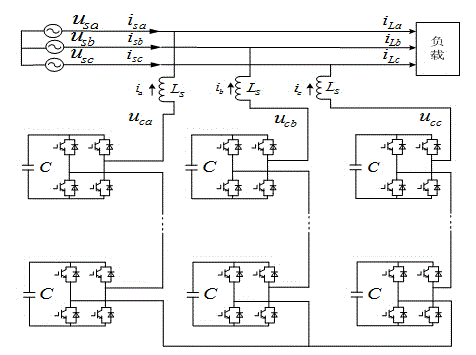
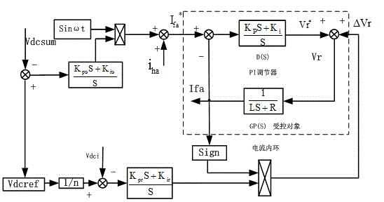
[0035] The switching control of the H-bridge cascaded converter adopts CPS-SPWM technology. The reactive power detection part adopts a closed loop detection circuit based on instantaneous reactive power theory. The control of the whole system includes two parts: current loop, voltage loop and DC side voltage equalization control by PI control on the AC side. The overall control block diagram is as follows figure 2 Shown.

[0036] The cascaded STATCOM adopts the idea of ​​decentralized control, which is a control method that combines the centralized control of the upper computer and the control of the lower computer. The upper computer control is mainly to realize the fast tracking and accurate calculation ...


PUM


Abstract

The invention provides a decentralized control method for an H-bridge cascaded power grid static reactive power compensator, and relates to a control method for a power grid compensator. The method comprises the decentralized control method, i.e. the control method of combination of upper computer centralized control and lower computer control. Two parts of current loop, voltage loop and DC side voltage equalizing control are realized by an AC side through PI control. Total DC voltage of each phase of the STATCOM is enabled to be stabilized at the designated value through reactive instruction adjustment of a voltage external loop. Current internal loop control adopts PI control on a controller so that current i of the AC side is detected to control energy inputted to a single-phase full-bridge DC side, and the voltage value of an inverter DC side is controlled by controlling active power flowing into a single-phase full bridge. The H-bridge-based cascaded STATCOM has great dynamic and static performance, high response speed, low harmonic content and great output characteristic so that a balance problem of voltage between phases of the DC side and capacitor voltage of all modules in the phases in the cascaded STATCOM can be effectively solved, and thus the decentralized control method for the H-bridge cascaded power grid static reactive power compensator has extremely high practical engineering value.

Description

Technical field [0001] The invention relates to a control method of a power grid compensator, in particular to a decentralized control method of an H-bridge cascade power grid static reactive power compensator. Background technique [0002] Static Var Compensator (Static Synchronous Compensator, STATCOM) belongs to a new generation of reactive power compensation device and is an important member of the FACTS family of flexible AC transmission systems. It has the advantages of fast response speed, low harmonic current, continuous adjustment of reactive power, small device size, low loss, etc., in the event of a grid failure or sudden load increase, it can dynamically and quickly provide voltage support to improve system safety and stability. Reduce the number of low-voltage release loads, prevent large-scale vicious power outages caused by transient voltage collapse, and can also play a role in suppressing voltage flicker, damping system oscillations, and improving power quality. ...

Claims


Application Information

Patent Timeline
Patent Type & Authority Applications(China)
IPC IPC(8): H02J3/18H02J3/01
CPCY02E40/10Y02E40/40
Inventor 关微张玉良郭洪月赵波张津铭陈明非张三勇李檀徐维东
Owner SHENYANG JIFU NEW ENERGY TECH DEV CO LTD
Learn More