
Noise-reduction horn

A speaker and noise reduction technology, which is applied in the direction of frequency/direction characteristic devices, etc., can solve problems such as difficulty, sound distortion, and distinction, and achieve the effects of high product qualification rate, undistorted sound, and good noise reduction effect

Inactive Publication Date: 2015-09-16
李永南
View PDF7 Cites 6 Cited by
  • Summary
  • Abstract
  • Description
  • Claims
  • Application Information

AI Technical Summary

Problems solved by technology

However, since the integrated miniature noise-reducing horn connects the miniature microphone embedded in the center of the ring-shaped speaker bracket, since the volume of the miniature microphone has a limit, it is impossible to make it infinitely smaller.
In this way, the miniature microphone will partially extend into the middle hole of the ring magnet, which makes it impossible for the volume of the ring magnet generating the magnetic field to be too small, and even a non-porous sheet magnet cannot be used, resulting in the diameter of the noise reduction horn. Generally, it can only be made more than 15mm. Now in some occasions, the minimum diameter of the noise reduction horn is required to reach 6mm, and it is impossible to realize the noise reduction horn with this structure.
[0005] And because the miniature microphone is embedded in the central position of the ring-shaped speaker bracket, the miniature microphone occupies and / or affects the position of the tuning hole of the integrated miniature noise reduction speaker, and further affects the sound quality of the integrated miniature noise reduction speaker. Sound quality, so that the sound it produces is not rich enough, and the sound it produces is distorted, making it difficult for people to distinguish the difference between mids, highs and lows in the sound it produces

Method used


Image

  • Noise-reduction horn
  • Noise-reduction horn

Examples


Embodiment Construction

[0022] In the description of the present invention, it should be understood that the orientation or positional relationship indicated by the terms "center", "upper", "lower", "front", "rear", "left", "right" etc. are based on The orientation or positional relationship shown in the drawings is only for the convenience of describing the present invention and simplifying the description, and does not indicate or imply that the referred device or element must have a specific orientation, be constructed and operated in a specific orientation, and therefore cannot be understood as Limitations on the Invention. In addition, the terms "first" and "second" are used for descriptive purposes only, and should not be understood as indicating or implying relative importance.

[0023] In the description of the present invention, it should be noted that unless otherwise specified and limited, the terms "installation", "connection" and "connection" should be understood in a broad sense, for ex...


PUM


Abstract

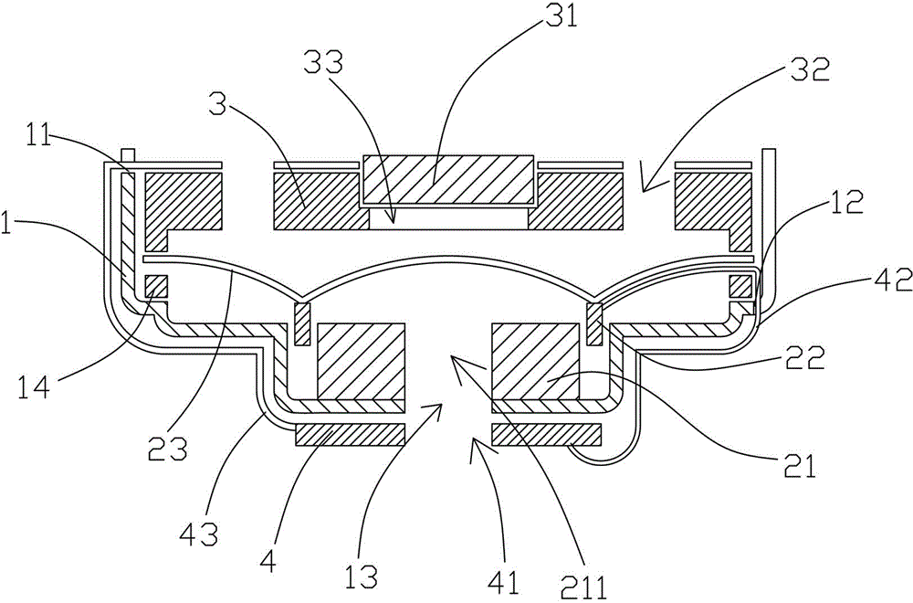
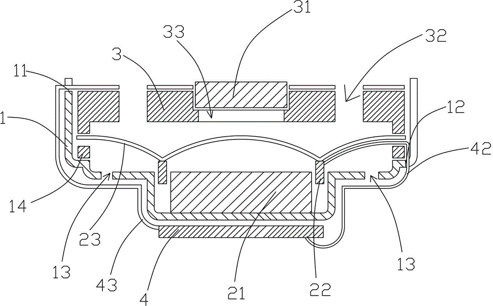
A noise-reduction horn comprises a horn unit and a microphone, the noise-reduction horn further comprises a horn protecting cover, the horn protecting cover is disposed on a sound outlet of a basic rack of the horn unit, the microphone is disposed on the horn protecting cover, and the horn protecting cover is further provided with a plurality of sound out-going holes. The microphone is disposed on the horn protecting cover, the volume of a magnet in the horn unit can be made to be very small, and a nonporous sheet-shaped magnet can also be used, so the diameter of the noise-reduction horn can be less than 15mm and even can reach 6mm; the design structure can be applied to products of a headset, even an in-ear noise-reduction earphone which is a smaller mechanism, and the like; a sound made by a vibrating diaphragm can be acquired and analyzed by the microphone at the first time, and the analysis and offset can be rapidly and fully performed on environment noises; and the noise-reduction horn has the advantages of simple structure, the good noise-reduction effect, large-scale mass production, the distortionless generated sound and the like, and the noise-reduction horn is suitable for being made with a large dimension or a small dimension.

Description

technical field [0001] The invention relates to a noise-reducing horn, which can simulate noise in the horn, and offset the anti-noise and noise in the earphone with equal amplitude and opposite phase, so as to improve the clarity of voice signals. Background technique [0002] Sound is generated by vibration and propagates in the air, and sound can be blocked, absorbed and counteracted by reverse vibration during the propagation process. Under normal circumstances, the speaker exists as a secondary sound source in the general environment, and the ambient noise becomes the primary sound source compared to other sounds. People can use the sound propagation characteristics and the principle of vibration cancellation to make the secondary sound source more effective than the primary sound source. The noise passed by the source is weakened and offset, that is to say, when the speaker vibrates when playing the sound source, it generates vibrations with the same frequency band and...

Claims


Application Information

Patent Timeline
IPC IPC(8): H04R1/20
Inventor 李永南
Owner 李永南
Learn More