Integrated oil-gas separator

A technology of oil and gas separators and separation elements, which is applied in separation methods, dispersed particle separation, chemical instruments and methods, etc., can solve the problems of high realization cost, large space occupation, and inability to use, and achieves the improvement of oil and gas separation efficiency and container. Effective volume control and better separation effect

Active Publication Date: 2015-09-23
JEREH OIL & GAS ENG
View PDF6 Cites 2 Cited by
  • Summary
  • Abstract
  • Description
  • Claims
  • Application Information

AI Technical Summary

Problems solved by technology

In order to achieve high-precision oil-gas separation, the existing technologies mainly include: first, adopt multi-stage oil-gas separators, and improve the oil-gas separation precision step by step through different structures; second, try to integrate different structures into the same oil-gas separator, For example, the post-separator with the patent No. ZL201320678903.6; the former requires a combination of multiple containers to meet the precision requirements, occupies a large space, and has a high cost of implementation; It cannot be used inside, and its cost is also high; in addition, the existing oil and gas separator has insufficient control over the gas to reroll the separated oil

Method used


Image

  • Integrated oil-gas separator
  • Integrated oil-gas separator

Examples


Embodiment Construction

[0028] The principles and features of the present invention are described below in conjunction with the accompanying drawings, and the examples given are only used to explain the present invention, and are not intended to limit the scope of the present invention.

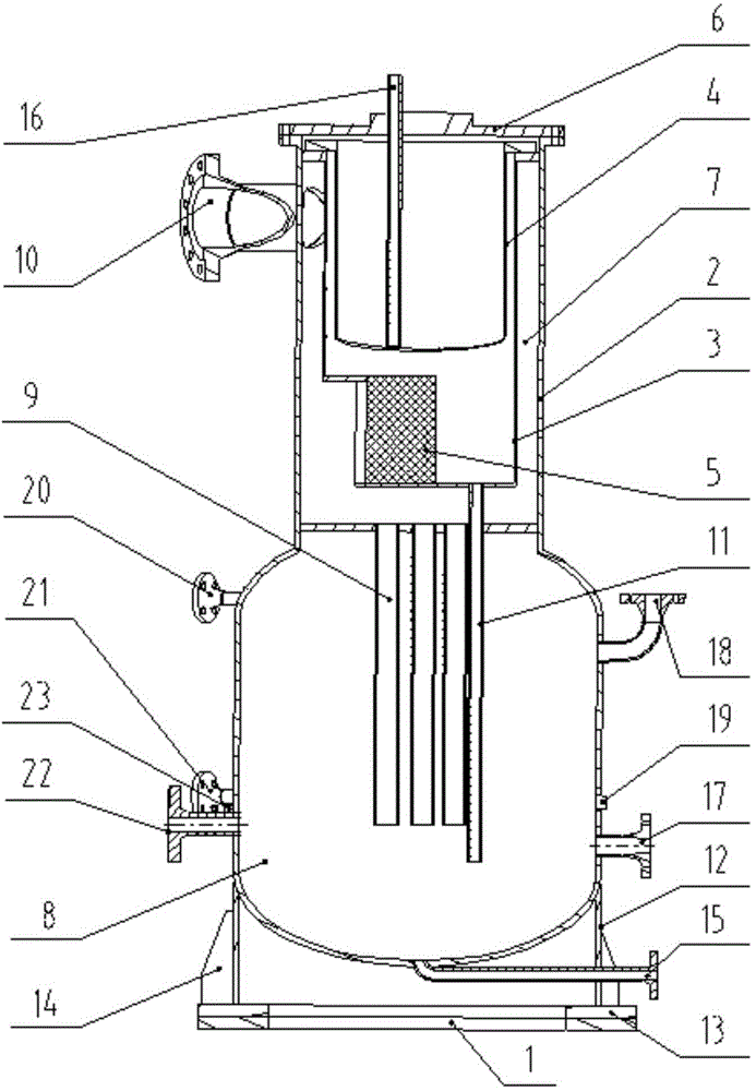
[0029] Such as figure 1 As shown, an integrated oil and gas separator includes a base 1, a cylinder body 2, a swirl cylinder 3, a filter element 4 and a blade separation element 5, the cylinder body 2 is fixedly placed on the upper end of the base 1, and the cylinder The upper end of the body 2 is detachably provided with a cylinder cover 6, and the upper and lower parts of the inner side of the cylinder body 2 are respectively provided with an upper chamber 7 and a lower chamber 8, and a partition is provided between the upper chamber 7 and the lower chamber 8. plate, the bottom of the upper chamber 7 is provided with a first liquid pipe 9 extending into the lower chamber 8, and the upper chamber 7 is provided with...


PUM


Abstract

The invention relates to an integrated oil-gas separator which comprises a base, a barrel body, a spiral-flow barrel, a filter element and a blade separation element, wherein the barrel body is fixedly arranged at the upper end of the base; a barrel cover is detachably arranged at the upper end of the barrel body; an upper cavity and a lower cavity are formed in the upper part and the lower part of the inner side of the barrel body respectively; a partition is arranged between the upper cavity and the lower cavity; a first liquid receiving pipe extending into the lower cavity is arranged at the bottom of the upper cavity; the upper cavity is provided with a gas inlet tangent with the wall of the barrel body and used for introducing an oil-gas mixture; the spiral-flow barrel is detachably arranged in the upper cavity; a vent hole is formed in the lower end of the spiral-flow barrel; the blade separation element is arranged at the vent hole in the inner side of the spiral-flow barrel; a second liquid receiving pipe extending into the lower cavity is arranged at the bottom of the spiral-flow barrel; the filter element is detachably arranged in the spiral-flow barrel and clung to the top of the inner side of the spiral-flow barrel; a gas outlet communicated with the interior of the filter element is arranged on the barrel cover. Compared with the prior art, the integrated oil-gas separator is compact in structure, high in oil-gas separation efficiency and controllable in separation precision, and oil-gas separation is carried out for three times.

Description

technical field [0001] The invention relates to the technical field of oil and gas processing equipment, in particular to an integrated oil and gas separator. Background technique [0002] With the rapid development of the oil and gas industry, the requirements for oil and gas separation technology are getting higher and higher. In order to achieve high-precision oil-gas separation, the existing technologies mainly include: first, adopt multi-stage oil-gas separators, and improve the oil-gas separation precision step by step through different structures; second, try to integrate different structures into the same oil-gas separator, For example, the post-separator with the patent No. ZL201320678903.6; the former requires a combination of multiple containers to meet the precision requirements, occupies a large space, and has a high cost of implementation; It cannot be used inside, and its cost is also high; in addition, the existing oil-gas separator is also insufficient for ...

Claims


Application Information

Patent Timeline
Patent Type & Authority Applications(China)
IPC IPC(8): B01D50/00
Inventor 田家栋陈保栋程纪杰张灵敏房海涛
Owner JEREH OIL & GAS ENG
Why Eureka
Try Eureka