Lifts

A lifting platform and support platform technology, applied in the field of lifting platform, can solve the problems of unsafety, high cost, unstable lifting, etc., and achieve the effect of high safety, simple structure and stable lifting

Active Publication Date: 2018-04-20
ANHUI ANKAI AUTOMOBILE
View PDF7 Cites 1 Cited by
  • Summary
  • Abstract
  • Description
  • Claims
  • Application Information

AI Technical Summary

Problems solved by technology

[0002] At present, lifting platforms or lifting devices for lifting heavy objects often adopt the form of gear ejector rods. This method is often complicated in structure, high in cost, and has factors such as laborious, high energy consumption, unstable lifting, and unsafety.

Method used


Image

  • Lifts
  • Lifts
  • Lifts

Examples


Embodiment 1

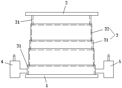
[0016] Such as figure 1 , figure 2 As shown, a telescoping tube 3 is arranged between the supporting platform 1 and the loading platform 2 .

[0017] In the case of setting a telescopic tube, the trachea includes first and second tubes 6, 7, one end of the first tube 6 is connected to the booster valve 4, and the other end of the first tube 6 is connected to the lowermost hard tube of the telescopic tube 3. The solid annular pipe 31 communicates, one end of the second pipe 7 links to each other with the pressure relief valve 5, and the other end of the second pipe 7 communicates with the hard annular pipe 31 at the bottom of the telescopic tube 3. That is to say, the first and second pipes are directly connected to the pipe wall of the hard annular pipe connected with the supporting platform, and the booster valve, the pressure relief valve, the telescopic pipe and the first and second pipes form a closed cavity.

Embodiment 2

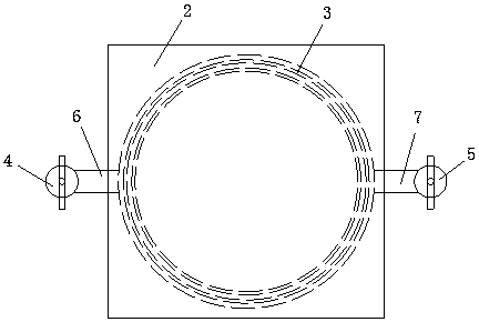
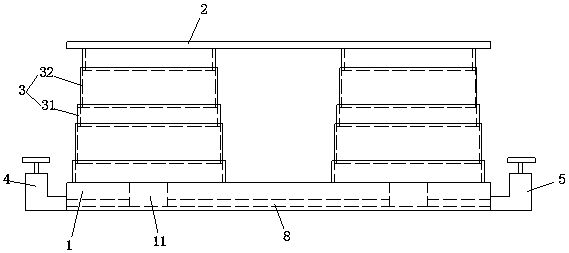
[0019] Such as image 3 , Figure 4 As shown, four telescopic tubes 3 are evenly arranged between the supporting platform 1 and the loading platform 2 .

[0020] In the case of setting four telescopic tubes, the supporting platform 1 is provided with four circular holes 11 respectively connected with the inner cavities of the four telescopic tubes 3. Preferably, the four circular holes should be arranged concentrically with the four telescopic tubes. Comprising connecting pipes 8 communicating with four circular holes 11 respectively, the connecting pipes 8 are arranged inside the support platform 1, that is, the four circular holes are connected through four connecting pipes 8 inside the supporting platform, and the four circular holes are connected with the four circular holes. The inner cavity of the root telescopic tube is communicated, and the connecting pipe 8 is provided with a booster valve 4 and a pressure relief valve 5, that is, the booster valve 4 and the pressure...


PUM


Abstract

The invention relates to a lifting platform which comprises a support table and a bearing table, the bearing table is arranged above the support table and is parallel to the support table, a telescopic pipe which connects the support table and the bearing table is arranged between the support table and the bearing table and connected with an air pipe, a pressurizing valve and a depressurizing valve are arranged on the air pipe, a sealed cavity is formed among the cavity of the telescopic pipe, the air pipe, the pressurizing valve and the depressurizing valve, the telescopic pipe is in a stretching state to jack the beating table upwards when the air pipe is inflated, and the telescopic pipe is in a retracting state to withdraw the bearing table downwards when the air pipe deflates. According to the technical scheme, pressurizing and depressurizing are used as a power source for the lifting platform, goods are lifted by the aid of the telescopic pipe which stretches or retracts with the change of the air pressure, and the lifting platform has the advantages that the structure is simple, the cost is low, energy consumption is small, lifting is stable, and the safety is high.

Description

technical field [0001] The invention relates to a lifting platform. Background technique [0002] At present, lifting platforms or lifting devices for lifting heavy objects often adopt the form of gear ejector rods. This method is often complicated in structure, high in cost, and has factors such as laborious work, high energy consumption, unstable lifting, and unsafety. Contents of the invention [0003] The object of the present invention is to provide a lifting platform, which is stable in lifting and high in safety. [0004] In order to achieve the above object, the present invention adopts the following technical solutions: including a supporting platform and a loading platform arranged above the supporting platform and parallel to the supporting platform, and there is a connection between the supporting platform and the loading platform. The telescopic tube, the telescopic tube is connected with the air pipe, the air pipe is provided with a booster valve and a press...

Claims


Application Information

Patent Timeline
Patent Type & Authority Patents(China)
IPC IPC(8): B66F7/08B66F7/28
CPCB66F7/085B66F7/28B66F2700/09
Inventor 李兵方明凤李孝卫胡洋任杰陈顺东丁传记洪洋
Owner ANHUI ANKAI AUTOMOBILE
Why Eureka
Try Eureka