Auxiliary moving device for bridge jacking construction and bridge jacking construction method

A technology of jacking construction and assisted movement, which is applied in the direction of bridges, bridge construction, erection/assembly of bridges, etc., and can solve problems such as easy stagnation, large longitudinal jacking force, and relatively harsh conditions

Active Publication Date: 2017-04-05
CHINA CONSTR SCI & IND CORP LTD
View PDF6 Cites 0 Cited by
  • Summary
  • Abstract
  • Description
  • Claims
  • Application Information

AI Technical Summary

Problems solved by technology

However, for a beam body 1 with a large self-weight (such as a bridge with a steel truss girder structure), a large longitudinal thrust is required, and under the action of such a large longitudinal thrust, stagnation is prone to occur, requiring continuous ground adjustment, reducing construction efficiency
For the beam body 1 adopting the variable cross-section structure 11, since the variable cross-section structure 11 is relatively simple, although the above functions can be realized in theory, in the actual construction process, various factors need to be considered (such as the variable cross-section structure The inclination of the lower surface, the coefficient of friction between the variable cross-section structure and the slideway 4, etc.), therefore, its requirements for the conditions of the construction site are more stringent
In the method of transitioning the beam body 1 using the slideway 4 with a slope, in addition to considering factors such as the slope of the slope, the coefficient of friction between the slope and the beam body 1, etc., this slideway with a slope 4 cannot be recycled. When the beam body 1 needs to continue to climb the next pier 3, a new slideway 4 with a slope needs to be reset on the next pier 3

Method used


Image

  • Auxiliary moving device for bridge jacking construction and bridge jacking construction method
  • Auxiliary moving device for bridge jacking construction and bridge jacking construction method
  • Auxiliary moving device for bridge jacking construction and bridge jacking construction method

Examples


Embodiment Construction

[0036] Specific embodiments of the present invention will be described in detail below in conjunction with the accompanying drawings. It should be understood that the specific embodiments described here are only used to illustrate and explain the present invention, and are not intended to limit the present invention.

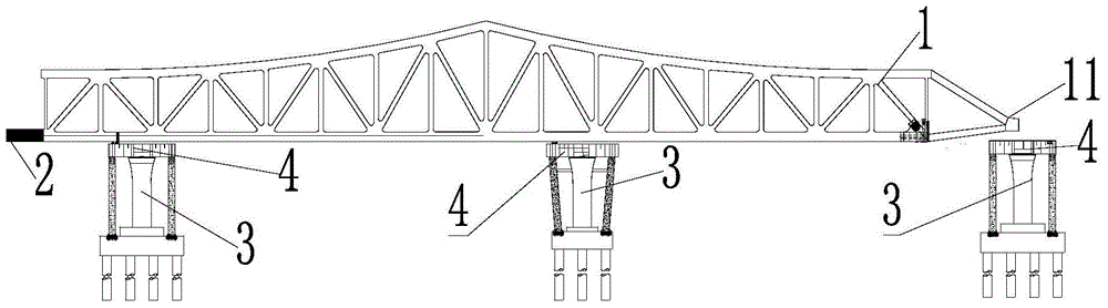
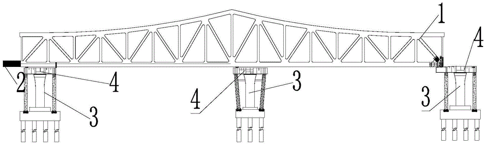
[0037] In the present invention, unless stated otherwise, the used orientation words such as "up and down" usually refer to the up and down in the height direction of each component when it is in use; "inside and outside" refers to Relative to the inside and outside of the outline of each component itself; "front and rear" refer to front and rear in the direction of movement of the beam body 1, but the above-mentioned orientation words are not used to limit the present invention.

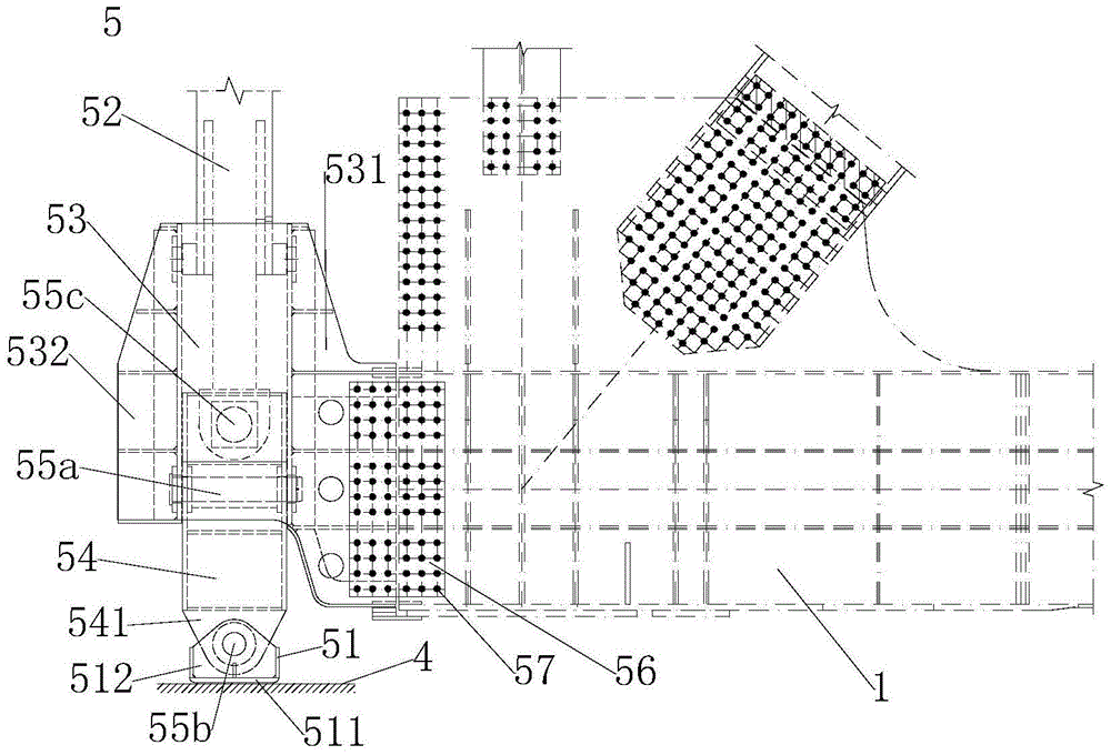
[0038]On the one hand, according to a specific embodiment of the present invention, there is provided an auxiliary mobile device for bridge pushing construction, wherein the auxiliary...


PUM


Abstract

The invention relates to the field of bridge construction, and discloses an auxiliary moving device and method for pushing construction of a bridge. The auxiliary moving device (5) is used for lifting the height of the front end of a bridge body (1) of the bridge. The auxiliary moving device (5) comprises a base (51) which is used for being supported on a foundation and can move on the foundation, a lifting device (52) which comprises a first part and a second part which can be unfolded and folded relatively, and a connecting fitting (53), wherein the base (51) is connected to the first part and can be in contact in the foundation or leave the foundation through the unfolding and the folding of the lifting device (52); the connecting fitting (53) is connected to the second part and is provided with a connecting part (531) for being connected with the front end of the bridge body (1). The auxiliary moving device provided by the invention can enable the bridge body to climb up the next pier successfully, so that the construction efficiency is improved.

Description

technical field [0001] The invention relates to the field of bridge construction, in particular to an auxiliary moving device and a pushing construction method for bridge pushing construction. Background technique [0002] In the field of bridge construction, the jacking construction method is mostly used in the construction of prestressed reinforced concrete, steel truss and other cross-section continuous beam bridges and cable-stayed bridges. The construction method that makes the beam body pass through the temporary sliding bearing surface of each pier top to be in place. In the jacking construction method, because the downward deflection of the beam body at the maximum cantilever is too large, the lower surface of the front end of the beam body is lower than the upper surface of the next pier. Pushing cannot make the girder climb to the next pier. To solve this problem, one or a combination of the following two traditional methods are often used: [0003] A variable s...

Claims


Application Information

Patent Timeline
Patent Type & Authority Patents(China)
IPC IPC(8): E01D21/06
Inventor 李周周轶张鹏危媛丞
Owner CHINA CONSTR SCI & IND CORP LTD
Why Eureka
Try Eureka