Electromagnetic high vacuum inflation valve

A high-vacuum, inflatable valve technology, applied in the direction of valve details, control valves, valve devices, etc., can solve the problems of difficulty in ensuring the airtightness of the vacuum system and low work efficiency, and achieve the solution of automatic control of the vacuum degree, reliable control, and solution The effect of low efficiency in the vacuum state

Active Publication Date: 2017-11-21
SHANGHAI LEIHANG MASCH MFG CO LTD
View PDF5 Cites 0 Cited by
  • Summary
  • Abstract
  • Description
  • Claims
  • Application Information

AI Technical Summary

Problems solved by technology

The work efficiency is very low with the manual inflation method, and the automatic control technology cannot be used, and the inflation valve is connected to the vacuum system to quickly and accurately control the vacuum degree of the vacuum system
If a general solenoid valve is used, it cannot be flexibly connected to the air and vacuum system when inflation is required; and it is difficult to ensure the airtightness of the vacuum system when the inflation is stopped.

Method used


Image

  • Electromagnetic high vacuum inflation valve
  • Electromagnetic high vacuum inflation valve
  • Electromagnetic high vacuum inflation valve

Examples


Embodiment approach 1

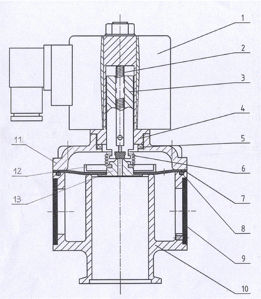
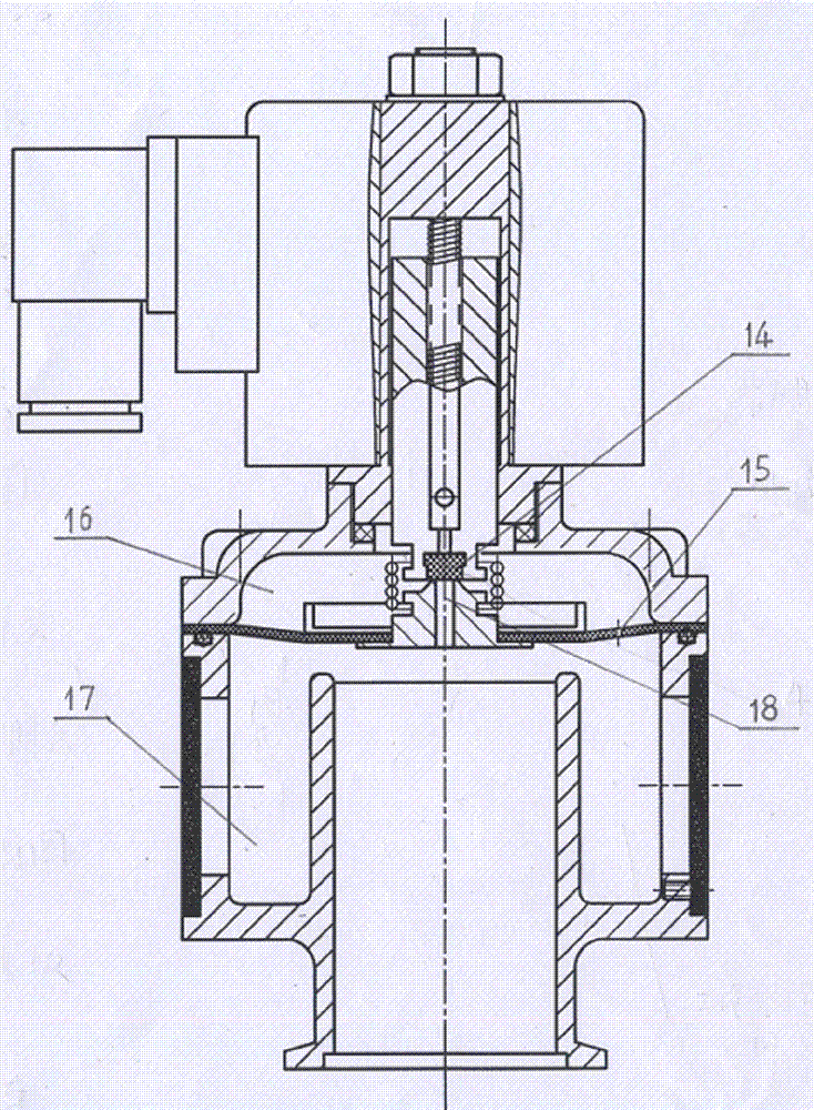
[0021] Such as figure 1 , 2 As shown, an electromagnetic high vacuum inflation valve includes an electromagnetic combination 1, an upper spring 2, an armature 3, a valve core 4, a small sealing ring 5, a lower spring 6, a cloth diaphragm 7, a large sealing ring 8, and a filter plate 9. Main body 10, upper cover 11, membrane cloth pressure plate 12, membrane seat 13 and wear-resistant plug 14. The armature 3 is slidingly matched with the valve core 4, and the upper spring 2 is installed in the inner hole of the armature 3.

[0022] The diaphragm seat 13 has a central hole 18 , and the cloth diaphragm 7 has a small vent hole 15 , the diameter of the small vent hole 15 is smaller than the diameter of the central hole 18 of the diaphragm seat 13 .

[0023] The lower end of the valve core 4 is fastened on the loam cake 11, and the loam cake 11 and the main body 10 are fastened with screws. The periphery of the cloth diaphragm 7 is compressed between the upper cover 11 and the ma...

Embodiment approach 2

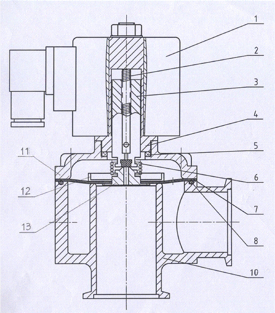
[0031] Such as image 3 , 4 As shown, the electromagnetic high-vacuum inflatable valve with large inflation capacity is connected to the air filter (not shown in the figure) on three sides and closed on one side on the four side windows of the main body 10, or connected to the air filter (not shown in the figure) on two sides and closed on both sides. , or one side is connected to the air filter (not shown in the figure) and three sides are closed.

[0032] The action process of the electromagnetic high vacuum inflation valve is:

[0033] Such as figure 1 , 3 As shown, when the electromagnetic combination 1 is de-energized, the armature 3 is pressed down against the diaphragm seat 13 due to the elastic force of the upper spring 2 . Simultaneously, the tension force of the lower spring 6 presses the diaphragm seat 13 downwards, forcing the cloth diaphragm 7 to be close to the vacuum nozzle in the main body 10 . At this time, the air entering the working gas chamber 17 from...


PUM


Abstract

The invention relates to an electromagnetic high-vacuum inflation valve. The electromagnetic high-vacuum inflation valve comprises an electromagnetic assembly, an armature, a valve element, an upper cover, a cloth clamping membrane, a membrane pressing plate, a membrane base, a filter plate, a body and the like. When the vacuum state of a vacuum system needs to be damaged and air is injected, the electromagnetic assembly is powered on, the valve element sucks the armature upwards, the gas pressure in a back pressure chamber and the gas pressure in a working gas chamber are changed, the membrane base and the cloth clamping membrane are disengaged from a pipeline opening in the body, and air entering the filter plate or an air filter is injected into the vacuum system. When the vacuum degree of the vacuum system decreases to a preset value, the electromagnetic assembly is powered off, force of an upper spring is downward, the cloth clamping membrane presses the pipeline opening in the body, and the vacuum system is closed. The electromagnetic high-vacuum inflation valve is connected into a vacuum pipeline, and the vacuum degree of the vacuum system can be damaged or controlled in time according to presetting.

Description

technical field [0001] The invention relates to an inflation valve used in a vacuum system, in particular to an electromagnetic high vacuum inflation valve. Background technique [0002] The electromagnetic high vacuum inflation valve is a new valve in the vacuum system. When the vacuum system needs to destroy the vacuum chamber, the manual inflation method is often used at present. With the method of manual inflation, the work efficiency is very low, and the automatic control technology cannot be used to connect the vacuum system with the inflation valve to quickly and accurately control the vacuum degree of the vacuum system. If a general solenoid valve is used, it cannot be flexibly connected to the air and vacuum system when inflation is required; and it is difficult to ensure the airtightness of the vacuum system when the inflation is stopped. Contents of the invention [0003] The object of the present invention is to provide an electromagnetic high vacuum inflation...

Claims


Application Information

Patent Timeline
Patent Type & Authority Patents(China)
IPC IPC(8): F16K15/20F16K31/06F16K51/02B01D46/00
CPCB01D46/00F16K15/202F16K31/0672F16K51/02
Inventor 张修枫梁跃跃秦杰
Owner SHANGHAI LEIHANG MASCH MFG CO LTD
Why Eureka
Try Eureka