Profiled clamp

一种异形、夹头的技术,应用在异形夹领域,能够解决不好外观、收紧力异形夹-法兰系统分散性/变化影响、头部接触片意外变形等问题

Active Publication Date: 2015-09-23
NORMA GERMANY GMBH
View PDF7 Cites 2 Cited by
  • Summary
  • Abstract
  • Description
  • Claims
  • Application Information

AI Technical Summary

Problems solved by technology

then there is a risk of unintentional deformation of the head contacts
On the one hand, this leads to a bad appearance
On the other hand there is the risk that the collets will no longer be aligned parallel to each other, which in some cases can negatively affect the tightening force and dispersion / variation of the profiled clamp-flange system

Method used


Image

  • Profiled clamp
  • Profiled clamp
  • Profiled clamp

Examples


Embodiment Construction

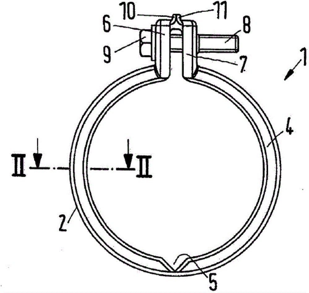
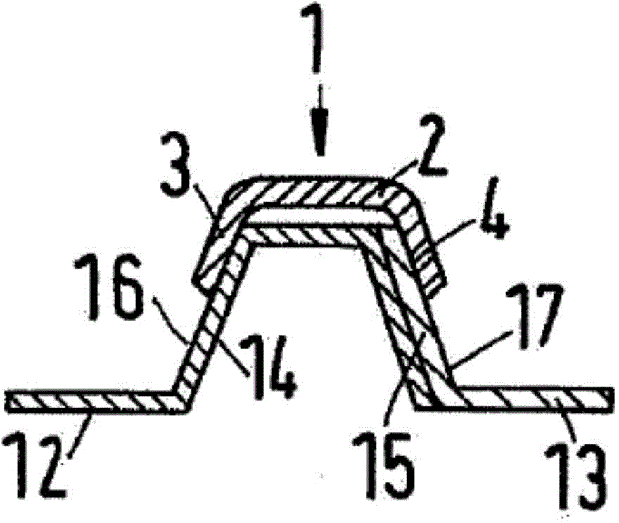
[0017] The profile clip 1 has a clip 2 which has radially inwardly running sides 3 , 4 at its axial ends. Such as figure 1 As shown, the sides can have interruptions 5 in the circumferential direction, whereby the clip 2 can be bent. However, the clip 2 can also be constructed in the circumferential direction from several parts.

[0018] The clamp 2 has a clamping head 6 , 7 at its two circumferential ends respectively. A tightening device in the form of a bolt 8 is guided through the collet 6 and is screwed onto a thread on the other collet 7 . Of course, the nut can also be screwed onto the end of the screw 8 protruding from the collet 7 . The screw 8 has a head 9 which, as in figure 1 In the shown tightened state, it bears against the outside of the collet 6 (in the circumferential direction).

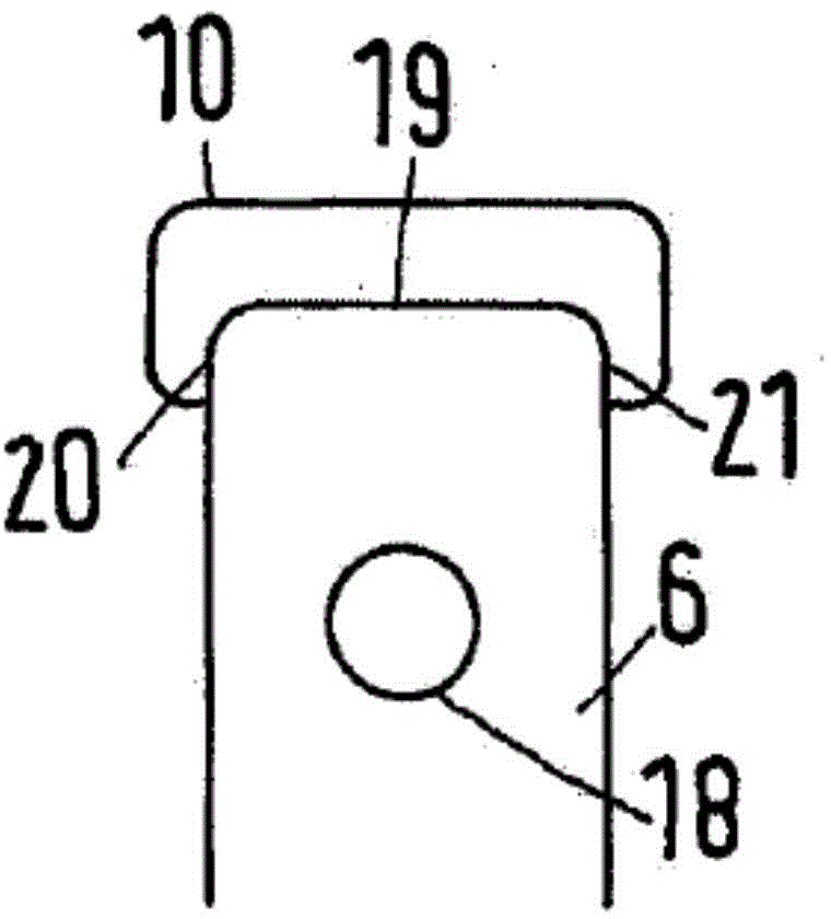
[0019] Each collet 6 , 7 has a head contact piece 10 , 11 . The two head contact pieces 10 , 11 abut against each other in the tightened state of the profile clip. In this ca...


PUM


Abstract

A profile clamp is disclosed having an annular clamping band that comprises two circumferential ends having respectively one tensioning head (6) and, at its axial ends, flanks sloped radially inwards, wherein the tensioning heads (6) are connected to one another by a tensioning device and at least one tensioning head (6) comprises a head contact tab (10). The object is to reduce the requirements for precision during installation. For this purpose, it is provided that the head contact tab (10) projects past the tensioning head (6) on at least one side in an axial direction.

Description

technical field [0001] The invention relates to a profile clamp with an annular clip having two circumferential ends each with a clip and sides inclined radially inwards at its axial ends, wherein the clip The collets are connected to each other by tightening means, and at least one of the collets has a head contact piece radially protruding from the collet. Background technique [0002] A profile clip of this type is disclosed, for example, in patent document DE 10 2012 009 256 A1. [0003] Profile clamps are often used to create so-called "tapered flange connections". In a conical flange connection, two elements to be connected each have a conical flange at their adjacent ends, the back of which is beveled. The profile clips are placed around the tapered flanges against each other so that the sides can act on the back of the tapered flanges. If the tightening device is operated and the diameter of the clamp is reduced, the side acts on the back of the flange based on an...

Claims


Application Information

Patent Timeline
Patent Type & Authority Applications(China)
IPC IPC(8): F16L23/04
CPCF16B2/08F16L23/08F16L23/04Y10T24/44239F16B7/0406
Inventor 曼努埃尔·博杜安琳达·布莱德邦德格里特·V·布赖滕巴赫赫尔穆特·格伯特托马斯·雷格尔
Owner NORMA GERMANY GMBH
Why Eureka
Try Eureka