Rainfall sensor

A rain sensor and container technology, applied in the field of measurement, can solve problems such as multi-maintenance and manual intervention, reduced measurement accuracy, complex manual cleaning, etc., and achieve the effects of improving measurement efficiency and quality, improving measurement accuracy, and improving measurement range.

Active Publication Date: 2015-09-23
宋大权
View PDF6 Cites 4 Cited by
  • Summary
  • Abstract
  • Description
  • Claims
  • Application Information

AI Technical Summary

Problems solved by technology

During the use of common rain sensors, due to the rain mixed with various impurities such as dust and grass seeds, the tipping bucket rain sensors are often blocked, and more complicated manual cleaning is often required
Once blocked, the accuracy of the rain sensor will exceed the allowable range, and even cause its damage
Although most of the existing weighing rain sensors do not have the problem of clogging, the capacity of the rain collection container is limited, especially when the rainfall is measured, frequent manual drainage is required, and more maintenance and manual intervention are still required to ensure its continuous normal operation
[0003] The tipping buc

Method used


Image

  • Rainfall sensor
  • Rainfall sensor
  • Rainfall sensor

Examples


Embodiment Construction

[0020] Embodiments of the present invention will be described in detail below with reference to the accompanying drawings.

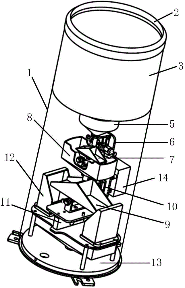
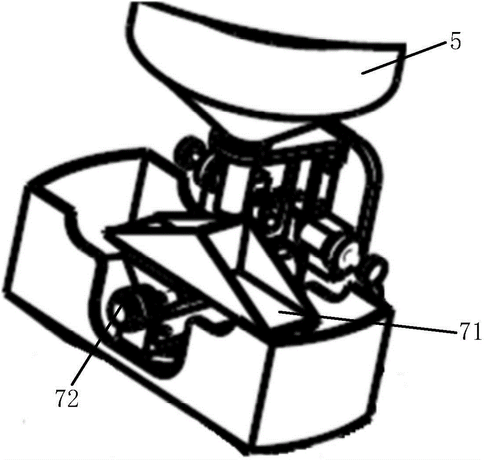
[0021] figure 1 A schematic structural diagram of the rain sensor of the present invention is shown. figure 2 A schematic structural view of the first collecting funnel and the anti-blocking device of the rain sensor of the present invention is shown.

[0022] refer to figure 1 and 2 , the structure of a rain sensor in the embodiment of the present invention is specifically:

[0023] The outer cylinder 1, the rain receiving port 2 located at the top of the outer cylinder 1, the first collecting funnel 3 located below the rain receiving port 2, the anti-blocking device 4 located at the bottom of the first collecting funnel 3, and the second collecting funnel located below the anti-blocking device 4 Collection funnel 5, measurement sensor switch 7 located below the second collection funnel 5, first water collection funnel 8 below the measurement senso...


PUM


Abstract

The invention relates to a rainfall sensor, which comprises an outer cylinder, a rain bearing opening located at the top part of the outer cylinder, a first collecting funnel, an anti-blocking device located at the bottom part of the first collecting funnel, a second collecting funnel located below the anti-blocking device, a measurement sensing switch located below the second collecting funnel, a first water collecting funnel located below the measurement induction switch, a weighing container located below the first water collecting funnel, a weighing induction unit arranged in the width direction of the weighing container, a load component located at the bottom part of the weighing container, a second water collecting funnel located below the load component, a base plate located at the bottom part of the outer cylinder, a vertical plate arranged on the base plate, and a pressing unit fixed on the vertical plate. The rainfall sensor provided by the invention reduces usage of tubular and porous structures, reduces locking circumstances, uses the load component to act as a weighing device, measures the rainfall by adopting resistance strain weighing technologies, and can improve the measurement accuracy.

Description

technical field [0001] The invention relates to the technical field of measurement, in particular to a rain sensor. Background technique [0002] The rain sensor (rain gauge) is the main equipment used for rainfall observation, which can measure the rainfall and rain intensity per unit time. At present, the instruments and equipment used for automatic rainfall measurement are mainly tipping bucket type (including single tipping bucket and double tipping bucket) and weighing type rain sensor in terms of measurement methods. During the use of common rain sensors, due to the rainwater mixed with various impurities such as dust and grass seeds, the tipping bucket rain sensors are often blocked, and more complicated manual cleaning is often required. Once blocked, the accuracy of the rain sensor will exceed the allowable range, and even cause its damage. Although most of the existing weighing rain sensors do not have the problem of clogging, the capacity of the rain collection ...

Claims


Application Information

Patent Timeline
IPC IPC(8): G01W1/14
CPCG01W1/14
Inventor 宋大权
Owner 宋大权
Why Eureka
Try Eureka