
Circuit breaker

A circuit breaker and moving contact technology, which is applied to circuit breaker components, protective switch operation/release mechanisms, etc., can solve the problems of long arc movement time, reduced breaking capacity of circuit breakers, and poor arc extinguishing capacity of arc extinguishing chambers, etc.

Active Publication Date: 2015-09-23
ZHEJIANG CHUANGQI ELECTRICAL CO LTD
View PDF4 Cites 17 Cited by
  • Summary
  • Abstract
  • Description
  • Claims
  • Application Information

AI Technical Summary

Problems solved by technology

The circuit breakers in the prior art have the following defects: ① When the arc is introduced into the arc extinguishing chamber and divided by the arc extinguishing grid, and then exported from the other end, due to the lack of corresponding protection and isolation, the arc is short-circuited and reignites again. The arcing time of the arc is too long, which will reduce the breaking capacity of the circuit breaker
②The magnetic field force of the arc introduced into the arc extinguishing chamber is weak, and the arc striking effect is poor, which makes the arc move for a long time, which leads to serious damage to the contact system and arc striking system, and affects the breaking capacity of the circuit breaker
③ The arc extinguishing ability of the arc extinguishing chamber is poor, the arc extinguishing chamber is seriously damaged, the arc extinguishing cover is easy to burst, and the speed of the arc entering the arc extinguishing chamber is slow, resulting in poor arc extinguishing effect
④ Due to the lack of an energy storage system in the operating mechanism, the circuit breaker will cause the contacts to bounce during the closing process, causing serious damage to the contacts and reducing the service life of the product

Method used


Image

  • Circuit breaker
  • Circuit breaker
  • Circuit breaker

Examples


Embodiment Construction

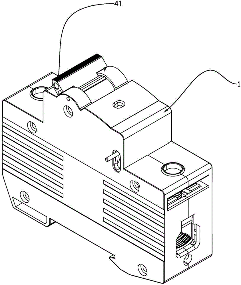
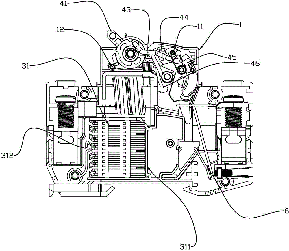
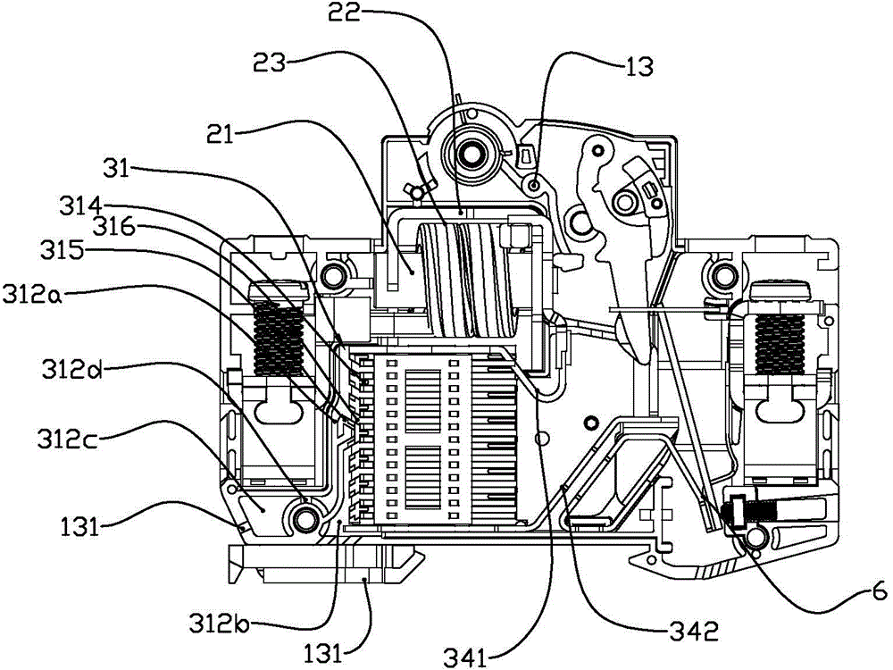
[0040]Specific embodiments of the present invention such as Figure 1-16 Shown is a circuit breaker, including a housing 1, a contact mechanism, an arc extinguishing system, an operating mechanism and a magnetic tripping mechanism. The contact mechanism includes a moving contact 51 and a static contact 52, and the moving contact 51 is provided with a moving contact At point 511, the static contact 52 is provided with a static contact 521. The arc extinguishing system includes an arc extinguishing chamber 31. The arc extinguishing chamber 31 is provided with an arc extinguishing grid 32, an arc extinguishing cover 33 and an arc strike assembly. The arc strike assembly includes an upper The arc leading piece 341 and the lower arc leading piece 342, one end of the upper arc leading piece 341 is located above the arc extinguishing chamber 31, and the other end of the upper arc leading piece 341 is bent upwards to connect with the static contact 52, and the static contact 521 is arr...


PUM


Abstract

The invention discloses a circuit breaker which comprises a housing, a contact mechanism, an arc extinction system, an operation mechanism and a magnetic tripping mechanism, wherein the contact mechanism comprises a dynamic contact and a static contact; a dynamic contact point is arranged on the dynamic contact; a static contact point is arranged on the static contact; the arc extinction system comprises an arc extinction system chamber; the arc extinction chamber is provided with an arc extinction grid-plate, an arc isolation plate and an arc striking assembly; the arc striking assembly comprises an upper arc striking plate and a lower arc striking plate; the lower arc striking plate is connected with a bimetallic strip; the bimetallic strip is matched with the dynamic contact in a linkage manner; the operation mechanism comprises a handle, a main bracket, a linkage assembly and a lock catch assembly; the lock catch assembly comprises a lock catch and a jump catch; the magnetic tripping mechanism comprises an iron core, a coil and a magnetic yoke; the arc extinction chamber comprises an arc inlet end and an arc outlet end; the arc outlet end is provided with arc outlet shunting partition regions which are a first arc outlet region and a second arc outlet region respectively; and arc guide outlets communicated with the first arc outlet region and the second arc outlet region are formed in the housing. The circuit breaker has the advantages of good breaking capacity, excellent arc extinction effect, safety and reliability.

Description

technical field [0001] The invention belongs to the technical field of circuit breakers, in particular to a circuit breaker with good arc ignition and arc extinguishing effects and high breaking capacity. Background technique [0002] A circuit breaker is a switch device used to cut off and connect the load circuit, and cut off the fault circuit to prevent the expansion of the accident, so as to ensure the safe operation of the load circuit. The structure of the circuit breaker mainly includes housing, contact mechanism, arc extinguishing system, operating mechanism and magnetic tripping mechanism. The contact mechanism includes moving contacts and static contacts. The moving contacts are equipped with moving contacts and static contacts. There is a static contact on the top; the arc extinguishing system includes an arc extinguishing chamber, and the arc extinguishing chamber is equipped with an arc extinguishing grid, an arc extinguishing cover and an arc striker; the opera...

Claims


Application Information

Patent Timeline
IPC IPC(8): H01H71/40H01H73/18
CPCH01H71/40H01H73/18
Inventor 沈玉文陆建军蔡寄文戴安彩
Owner ZHEJIANG CHUANGQI ELECTRICAL CO LTD
Learn More