
A method of manufacturing a semiconductor device

A manufacturing method and semiconductor technology, applied in the direction of electrical components, etc., can solve problems such as insufficient silicon etching, high current, and influence on word line performance, and achieve the effects of improving yield, simplifying manufacturing process, and reducing etching load effect

Active Publication Date: 2018-09-21
SEMICON MFG INT (SHANGHAI) CORP
View PDF10 Cites 0 Cited by
  • Summary
  • Abstract
  • Description
  • Claims
  • Application Information

AI Technical Summary

Problems solved by technology

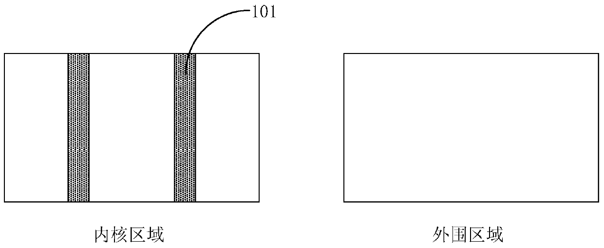
In the process of etching to form shallow trenches (active area etching), sub-trench issues (Sub-trench issue) may occur in the isolation area of ​​​​the peripheral area, that is, additional trenches are formed outside the shallow trenches
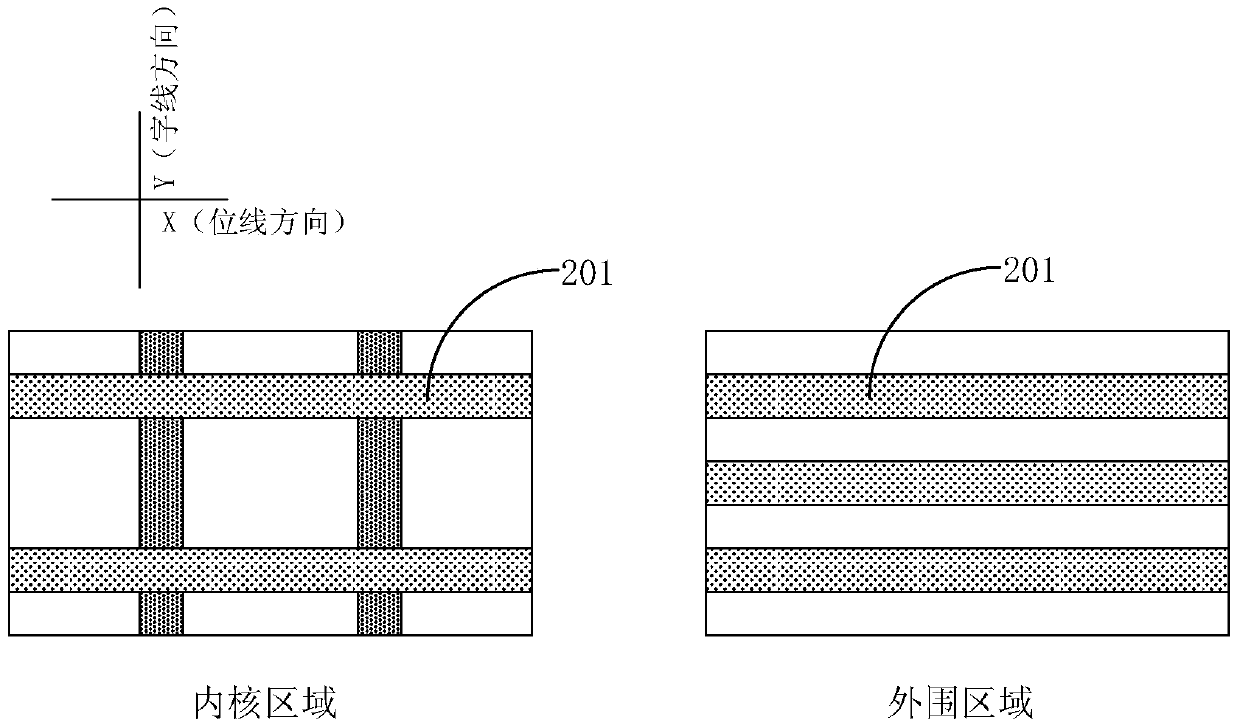
In addition, in the area where the deep trench isolation and the shallow trench isolation intersect in the core region, the silicon fence (Si fence) phenomenon is prone to occur, that is, there is a problem of insufficient silicon etching in the shallow trench
In addition, due to the relatively large depth of the deep trench isolation 201, it is often impossible to form a deep trench isolation that meets the requirements simply by a high-aspect-ratio oxide filling process. In the prior art, an annealing process is often added after the filling process. However, the high temperature annealing process will affect the performance of the word line and will cause high deep trench isolation pad current

Method used


Image

  • A method of manufacturing a semiconductor device
  • A method of manufacturing a semiconductor device
  • A method of manufacturing a semiconductor device

Examples


Embodiment Construction

[0055]In the following description, numerous specific details are given in order to provide a more thorough understanding of the present invention. It will be apparent, however, to one skilled in the art that the present invention may be practiced without one or more of these details. In other examples, some technical features known in the art are not described in order to avoid confusion with the present invention.

[0056] It should be understood that the invention can be embodied in different forms and should not be construed as limited to the embodiments set forth herein. Rather, these embodiments are provided so that this disclosure will be thorough and complete, and will fully convey the scope of the invention to those skilled in the art. In the drawings, the size and relative sizes of layers and regions may be exaggerated for clarity. Like reference numerals refer to like elements throughout.

[0057] It will be understood that when an element or layer is referred to...


PUM


Abstract

The invention provides a manufacturing method of a semiconductor device, and relates to the technical field of semiconductor storage. According to the manufacturing method of the semiconductor, a technology for forming a double-trench isolation structure is integrated into a standard CMOS technology, and the manufacturing technology of the semiconductor device is simplified; in addition, an etching load effect between a core area and a peripheral area in a shallow trench isolation forming process is reduced by means of technology optimization that shallow trench isolation is formed first and then deep trench isolation is formed, so that the yield rate of the semiconductor device is improved.

Description

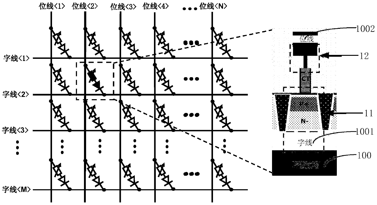
technical field [0001] The invention relates to the technical field of semiconductor storage, in particular to a method for manufacturing a semiconductor device. Background technique [0002] As a non-volatile memory, phase change memory (PCM) is widely used in the field of semiconductor storage technology due to its advantages in read and write speed, read and write times, data retention time, cell area, and multi-value realization. has been widely applied. The structure of a phase change memory in the prior art is as follows figure 1 As shown, a word line (word line) 1001 , a bit line (bit line) 1002 , a gate diode 11 and a phase change resistor 12 located on a semiconductor substrate 100 are included. Wherein, in the phase change memory, a dual trench isolated structure (dual trench isolated structure) for isolating the pass diode 11 is usually included. The main challenge of the prior art is how to fabricate the double trench isolation structure fully compatible with ...

Claims


Application Information

Patent Timeline
Patent Type & Authority Patents(China)
IPC IPC(8): H01L45/00
Inventor 张超
Owner SEMICON MFG INT (SHANGHAI) CORP
Learn More