A mechanically adjustable magnetic rotating machine

A technology of rotating electrical machines and magnetic adjustment, which is applied in the direction of electromechanical devices, mechanical energy control, and magnetic circuit rotating parts, etc., which can solve the problem of insufficient support for the large speed range of electric vehicles, reduce the reliability of permanent magnet motors, and reduce the efficiency of permanent magnet motors No demagnetization risk, high and weak magnetic field speed expansion capability, and improved reliability

Inactive Publication Date: 2018-12-28
LANZHOU JIAOTONG UNIV
View PDF5 Cites 0 Cited by
  • Summary
  • Abstract
  • Description
  • Claims
  • Application Information

AI Technical Summary

Problems solved by technology

[0003] The magnetic field of the permanent magnet motor is difficult to adjust. Although the permanent magnet magnetic field can be adjusted by weakening the magnetic field, the weakening field is still not enough to support the large speed operating range required by the electric vehicle, and the existence of the direct axis component of the stator current makes the stator The copper loss of the winding is greatly increased, which reduces the efficiency of the permanent magnet motor
On the other hand, in the process of field weakening and speed expansion, more or less demagnetization of the permanent magnet steel is inevitable, which reduces the reliability of the permanent magnet motor

Method used


Image

  • A mechanically adjustable magnetic rotating machine
  • A mechanically adjustable magnetic rotating machine
  • A mechanically adjustable magnetic rotating machine

Examples


Embodiment Construction

[0022] The present invention will be further described below in conjunction with accompanying drawing:

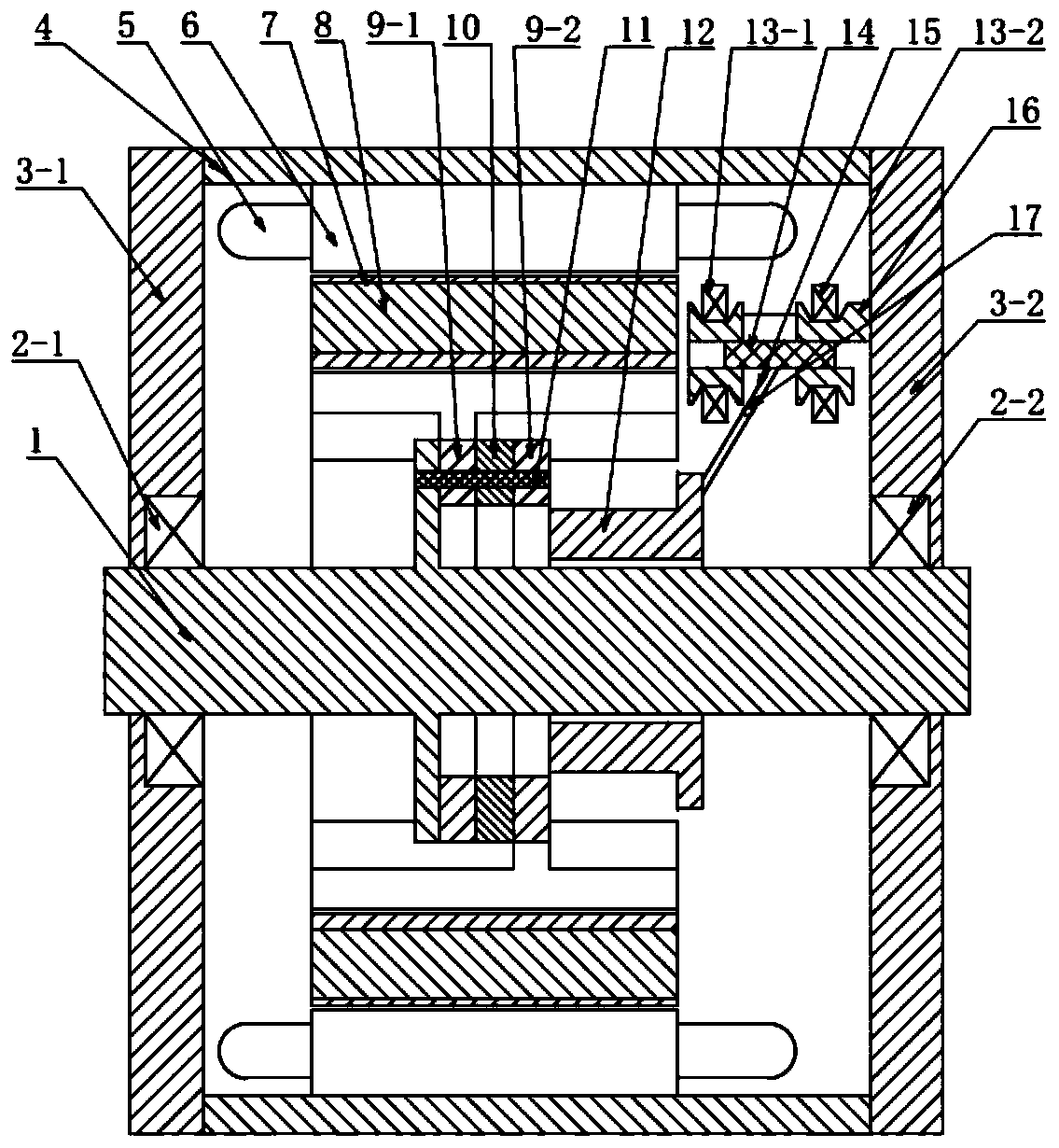
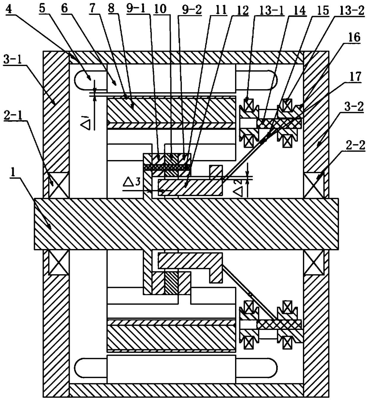
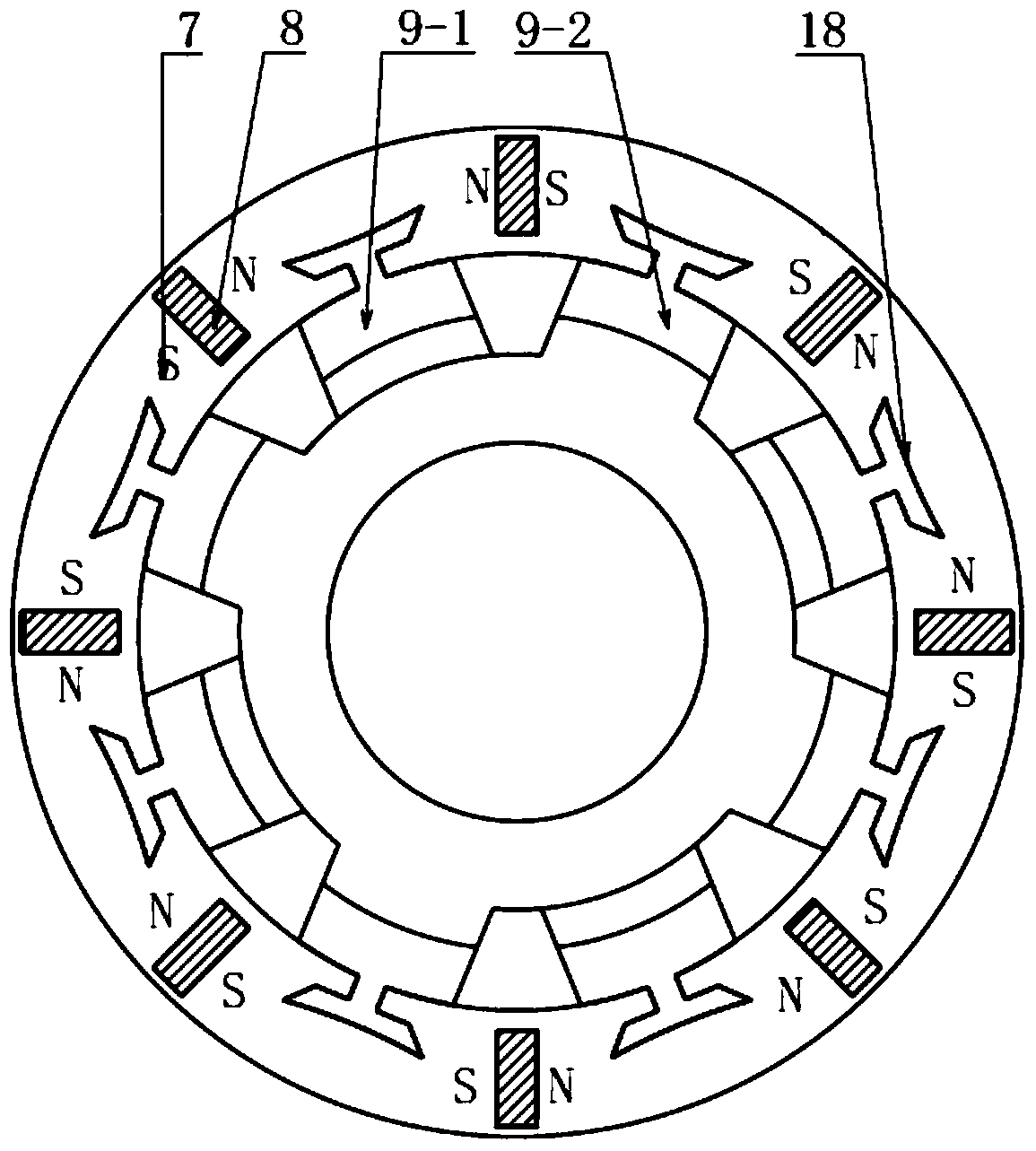
[0023] Such as Figures 1 to 4 As shown, a mechanical magnetic modulation rotating electrical machine described in the embodiment of the present invention includes a casing 4, a stator core 6, a rotor core 7, a rotating shaft 1, a movable magnetic yoke 12, and a mechanical solenoid valve for magnetic modulation. device; the stator core 6 is fixed on the casing 4; the rotor core 7 is embedded with a front salient pole 9-1 and a rear salient pole 9-2; the movable magnetic yoke 12 is located on the rotating shaft 1 between the front salient pole 9-1 and the rear salient pole 9-2, the mechanical solenoid valve magnetic adjustment device is connected to the movable magnetic yoke 12 and controls the movable magnetic yoke 12 to move axially along the rotating shaft 1 .

[0024] One end of the rotating shaft 1 is fixed on the first bearing end cover 3-1 through the first bearing ...


PUM


Abstract

The invention relates to the motor technology field and especially relates to a mechanical adjustable magnet type rotation motor. The motor comprises a rotor iron core, a rotating shaft, a movable magnetic yoke and a mechanical solenoid-valve adjustable-magnetic device. A front salient pole and a rear salient pole are embedded into the rotor iron core. The movable magnetic yoke is located between the front salient pole and the rear salient pole. The mechanical solenoid-valve adjustable-magnetic device is connected to the movable magnetic yoke and makes the movable magnetic yoke axially moves along the rotating shaft. The mechanical solenoid-valve adjustable-magnetic device makes the movable magnetic yoke axially moves along the rotating shaft so that on and off of a leakage flux path which is newly added in a permanent magnetic flux are realized. Further an effective magnetic flux of a motor air gap is indirectly controlled so that the motor possesses a good adjustable flux capability and high rotating speed operation is realized. When a traditional permanent magnetism motor carries out flux weakening speed expansion, a large straight shaft is needed to carry out demagnetizing current. By using the rotation motor, the above problem is avoided. The motor is guaranteed to possess high efficiency and a high power factor. Permanent magnet steel has no demagnetization risks so that reliability of the motor is increased.

Description

technical field [0001] The invention relates to the technical field of electric motors, in particular to a mechanically adjustable magnetic rotating electric machine. Background technique [0002] Permanent magnet motors have been widely used in electric vehicle drive systems due to their advantages of high efficiency, high power density, and high power factor. The driving motor of new energy vehicles requires low-speed and high-torque output at low speeds; it needs to maintain constant power at high speeds, and low-speed and high-torque can meet the start-up of the whole vehicle, such as acceleration and climbing. High-speed constant power needs to be able to meet the maximum speed requirements of the vehicle, as well as overtaking at high speeds. [0003] The magnetic field of the permanent magnet motor is difficult to adjust. Although the permanent magnet magnetic field can be adjusted by weakening the magnetic field, the weakening field is still not enough to support th...

Claims


Application Information

Patent Timeline
Patent Type & Authority Patents(China)
IPC IPC(8): H02K7/00H02K1/24
Inventor 兰宏伟王娜
Owner LANZHOU JIAOTONG UNIV
Why Eureka
Try Eureka