
Iron removal device with automatic iron unloading function

A technology of iron remover and automatic unloading, applied in chemical instruments and methods, magnetic separation, solid separation, etc., can solve problems such as vicious tearing of belt conveyors, iron falling into coal flow, electromechanical accidents, etc., to reduce labor intensity of employees, The effect of removing iron sundries, reducing power consumption and equipment loss

Inactive Publication Date: 2015-09-30
CHINA SHENHUA ENERGY CO LTD +1
View PDF7 Cites 0 Cited by
  • Summary
  • Abstract
  • Description
  • Claims
  • Application Information

AI Technical Summary

Problems solved by technology

However, this traditional iron remover has the following defects: firstly, the iron removal belt of the iron remover is often in the running state for a long time. Unnecessary power consumption and equipment loss
Second, if the iron removing tape of the iron remover does not run for a long time, it needs to be started and stopped manually intermittently, that is, the driving motor of the iron remover tape will not be started under normal circumstances, and when the absorbed iron reaches a certain amount, start The iron remover throws out the iron remover and then stops the iron remover, and repeats the operation in this way, but often because there are too many adsorbed iron devices under the iron remover, and the manual cannot find it in time, the iron adsorbed by the iron remover falls into the coal flow again. Due to the accumulation of iron, long iron will span between the iron remover and the machine head of the tape machine, which will easily cause vicious tearing of the tape machine and cause serious electromechanical accidents

Method used


Image

  • Iron removal device with automatic iron unloading function
  • Iron removal device with automatic iron unloading function
  • Iron removal device with automatic iron unloading function

Examples


Embodiment Construction

[0023] The present invention will be described in detail below in conjunction with examples. Wherein the same components are denoted by the same reference numerals. It should be noted that the words "front", "rear", "left", "right", "upper" and "lower" used in the following description refer to the directions in the drawings, and the words "inner" and "outer ” refer to directions towards or away from the geometric center of a particular part, respectively.

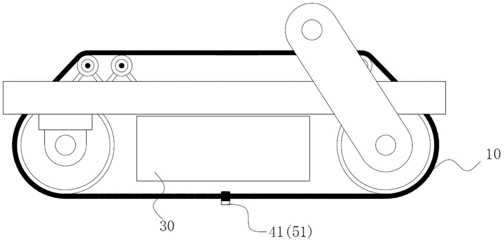
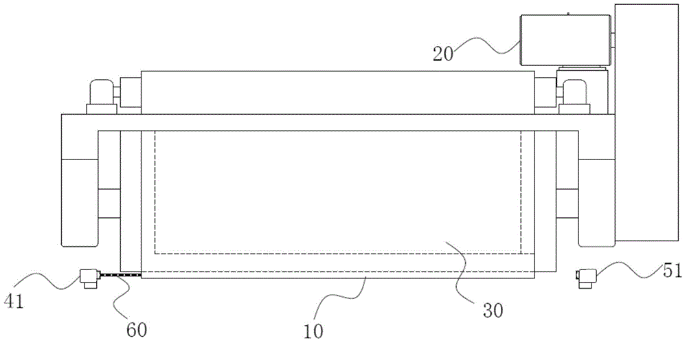
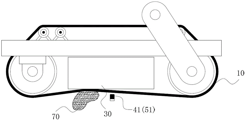
[0024] figure 1 It is the first preferred embodiment of the iron remover with automatic unloading function of the present invention; figure 2 yes figure 1 left view of image 3 yes figure 1 Schematic diagram of the working state of the iron remover in ; Figure 4 yes image 3 left view of . combine figure 1 , figure 2 , image 3 and Figure 4 As shown, the iron remover with automatic iron removal function provided by the present invention includes an iron removal tape 10, a drive motor 20, a magnet 30, sensin...


PUM


Abstract

The invention discloses an iron removal device with an automatic iron unloading function. The iron removal device comprises an iron unloading rubber belt and a driving motor for driving the iron unloading rubber belt. The iron unloading rubber belt comprises an adsorption face, a magnet is arranged on one side away from the adsorption face of the iron unloading rubber belt, and a gap is reserved between the magnet and the iron unloading rubber belt; and the iron removal device further comprises a sensing device and a controller. When the iron unloading rubber belt is close to or in contact with the magnet, an induction signal is generated; and according to the induction signal, the controller controls the driving motor; and a signal input end of the controller is in communication connection with the sensing device, and the control output end of the controller is electrically connected with the driving motor. According to the iron removal device, under the condition that the power consumption and equipment losses are reduced, adsorbed iron can be efficiently removed, and the effects that the energy is saved, the consumption is reduced, the service life of the iron removal device is prolonged, device safety is ensured, and labor intensity of personnel is reduced are achieved.

Description

technical field [0001] The invention relates to an iron remover with the function of automatically unloading iron. Background technique [0002] In the field of coal mining and washing and processing, it is inevitable that iron debris will be mixed into the coal flow. These iron debris are hard and sharp, causing serious damage to the safe operation of belt conveyors, crushers, scrapers and other equipment. Many coal enterprises have hundreds of thousands or even millions of equipment damages caused by ironware, so how to remove the ironware mixed in the coal flow is particularly important. [0003] At present, the permanent magnet iron remover with magnetism or the electromagnetic iron remover that can generate magnetism are generally used to absorb iron impurities in coal, so as to achieve the purpose of iron removal. In actual use, most of the iron removing tapes are used for iron removal operation, that is, after the iron remover absorbs the iron debris, the iron is not...

Claims


Application Information

Patent Timeline
Patent Type & Authority Applications(China)
IPC IPC(8): B03C1/02
Inventor 蒋涵元张金梁靳俊科周瑞通
Owner CHINA SHENHUA ENERGY CO LTD
Learn More