Photogravure press in combination production line

A technology of gravure printing machine and production line, which is applied in gravure rotary printing machine, printing machine, rotary printing machine and other directions, can solve the problems of product quality decline, printing production efficiency reduction, unreasonable structure design, etc., to improve performance and improve printing. The effect of production efficiency

Inactive Publication Date: 2015-09-30
刘海明
View PDF5 Cites 0 Cited by
  • Summary
  • Abstract
  • Description
  • Claims
  • Application Information

AI Technical Summary

Problems solved by technology

[0002] In the large-scale combined printing production environment, due to the unreasonable structural design of the drying device of the gravure printing machine, a drying device is installed on one side of each printing group, which directly leads to the phenomenon of false drying of the ink; the drying of the paper surface When the uniformity of the paper is poor, resulting in poor safety performance; some volatile organic compounds in the ink can not be completely volatilized
In the northern region in winter, the low temperature environment has a great impact on the ink, the viscosity of the ink increases, the fluidity slows down, the color and effect of the printed matter often fail to meet the design requirements, and the product quality declines. For the production method of multiple production lines combined printing , there is also the problem of poor coordination and maneuverability of the printing machine, which reduces the printing production efficiency

Method used


Image

  • Photogravure press in combination production line
  • Photogravure press in combination production line

Examples


Embodiment Construction

[0012] The technical solution of this patent will be further described in detail below in conjunction with specific embodiments.

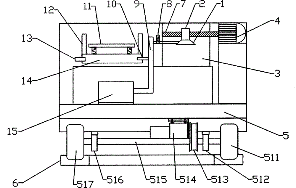
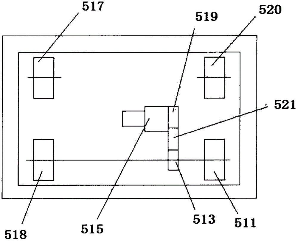
[0013] see Figure 1~2 , a gravure printing machine in a combined production line, comprising a printing machine frame body, an ink tank 12 is provided on the printing machine frame body, a plurality of springs are provided at the inner bottom of the ink tank 12, and a plurality of springs are arranged on the spring The baffle plate 11 is provided with a plurality of ink outlet holes on the baffle plate 11. The bottom end of the ink tank 12 is provided with a cavity 14, and the two ends of the cavity 14 are provided with an air inlet 10 and an air outlet 13. The tuyere 13 is provided with an air volume control panel; a hot air blower 15 is installed in the body, and the hot air blower 15 is connected with the air inlet 10 and the air outlet 1 in the oven 3 through the air duct 9; the oven 3 is arranged on one side of the body, Oven 3 is provided w...


PUM


Abstract

The invention discloses a photogravure press in a combination production line. The photogravure press comprises a press frame body. An ink groove is formed in the press frame body. A plurality of springs are arranged at the inner bottom end of the ink groove. A baffle is arranged on the springs. A cavity is formed in the bottom end of the ink groove. An air inlet and an air outlet are formed in the two ends of the cavity. An air volume control panel is arranged on the air outlet. A hot-air blower is installed inside the press body. The hot-air blower is connected with an air inlet and an air outlet head inside an oven through an air pipe. The oven is arranged on one side of the press body. A lead screw is arranged inside the oven. A nut is arranged on the lead screw. The bottom end of the nut is connected with the air outlet head. The frame body is fixedly connected with a mobile base through a connecting base. A longitudinal horizontal motion guide rail is installed below the mobile base. According to the photogravure press, the photogravure press can be conveniently and rapidly transferred to the position, where printing operation is needed, of the combination production line through the cooperation of the mobile base and the guide rail, and the printing production efficiency is greatly improved.

Description

technical field [0001] The invention relates to the technical field of printing machinery, in particular to a gravure printing machine in a combined production line. Background technique [0002] In the large-scale combined printing production environment, due to the unreasonable structural design of the drying device of the gravure printing machine, a drying device is installed on one side of each printing group, which directly leads to the phenomenon of false drying of the ink; the drying of the paper surface When the uniformity of the paper is poor, the safety performance is poor; some volatile organic compounds in the ink cannot be completely volatilized. In the northern region in winter, the low temperature environment has a great impact on the ink, the viscosity of the ink increases, the fluidity slows down, the color and effect of the printed matter often fail to meet the design requirements, and the product quality declines. For the production method of multiple prod...

Claims


Application Information

Patent Timeline
Patent Type & Authority Applications(China)
IPC IPC(8): B41F9/06
Inventor 刘海明
Owner 刘海明
Why Eureka
Try Eureka