Distributed type electric ducted fan flap lifting system and hovercar thereof

A ducted fan and flying car technology, applied in the field of flying cars, can solve the problems of the propeller without ducted ring protection, the propeller slip flow with slip flow twist, and the unfavorable power increase, so as to achieve a significant lift increase effect and a slip flow. Low speed, low impact effect

Inactive Publication Date: 2015-09-30
龙川
View PDF7 Cites 25 Cited by
  • Summary
  • Abstract
  • Description
  • Claims
  • Application Information

AI Technical Summary

Problems solved by technology

Since March 2015, NASA has started experimenting with a wing using a distributed electric propeller flap lift system. The wing has a total of 18 electric propellers, and the electric propellers are distributed on the leading edge of the wing to When the aircraft takes off and lands, the wings are powered up; however, the propeller

Method used


Image

  • Distributed type electric ducted fan flap lifting system and hovercar thereof
  • Distributed type electric ducted fan flap lifting system and hovercar thereof
  • Distributed type electric ducted fan flap lifting system and hovercar thereof

Examples


Embodiment Construction

[0026] The present invention will be further described in detail below in conjunction with the accompanying drawings and embodiments.

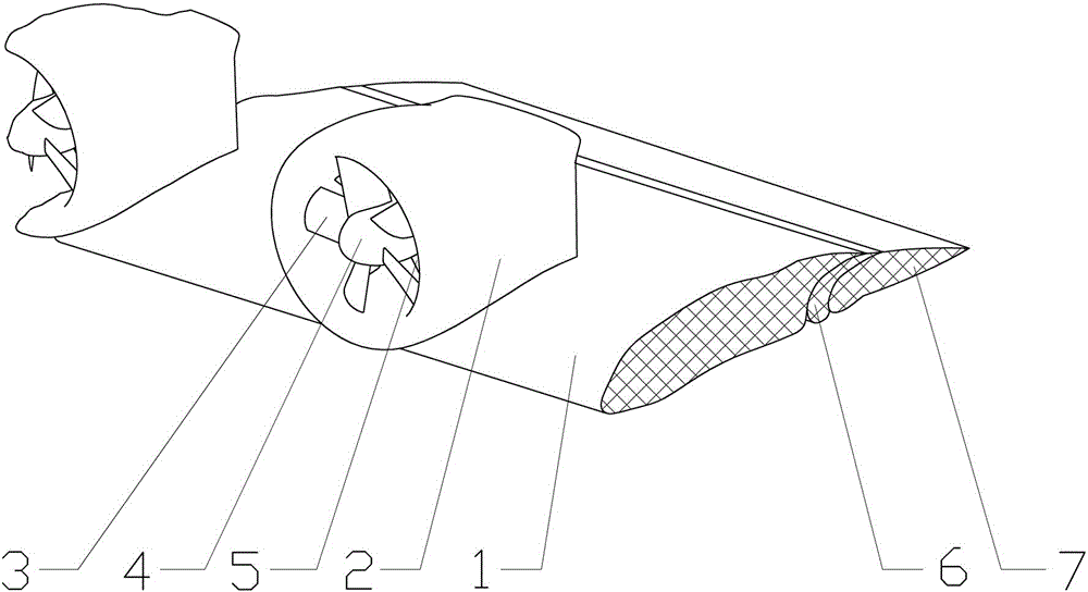
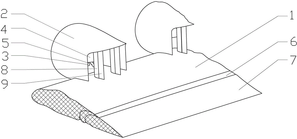
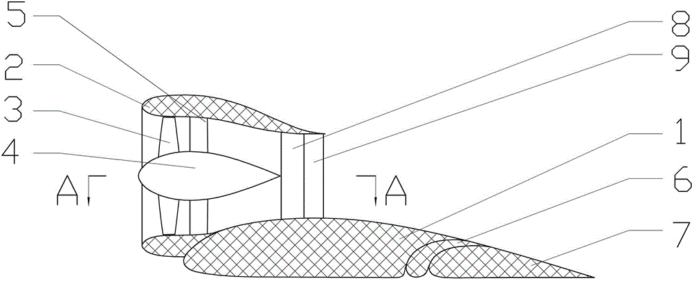
[0027] Such as figure 1 , 2 , 3, 4, 5, 6, 7, 8, 9, 10, and 11, the distributed electric ducted fan flap lift system of the present invention comprises a wing 1 and a culvert arranged on the leading edge of the wing 1 The duct fan, the duct fan includes duct 2, the fan 3 in the duct 2, the motor 4 driving the fan 3, the support plate 5 supporting the motor 4, the wing 1 has a trailing edge flap, and there are several duct fans, The leading edge of the wing 1 is linearly arranged at intervals of a certain distance; the leading edge of the duct 2 protrudes in front of the leading edge of the wing 1, and the trailing edge of the duct 2 is located at the position of the maximum thickness of the wing 1. The rear edge of the wing 1 corresponding to where the fan is located is provided with a trailing edge flap.

[0028] Due to the use of electric ...


PUM


Abstract

The invention discloses a distributed type electric ducted fan flap lifting system. The distributed type electric ducted fan flap lifting system is provided with a plurality of ducted fans which are in linear arrangement at the front edge of the upper wing surface of a wing at certain distances, the front edge of a duct stretches to be positioned in front of the front edge of the wing, the rear edge of the duct is located at the maximum thickness position of the wing, and a rear edge flap is arranged at the rear edge of the wing, corresponding to the position of the ducted fan. The distributed type electric ducted fan flap lifting system is safe and has low noise, small vibration, high lifting force and good economical efficiency during working. A hovercar adopting the distributed type electric ducted fan flap lifting system can realize vertical takeoff and landing, high-speed horizontal flight and smooth conversion between the vertical takeoff and landing state and the high-speed horizontal flight state.

Description

technical field [0001] The present invention relates to an externally blown flap increasing lift system, in particular to a distributed electric ducted fan flap increasing system and a flying car using the distributed electric ducted fan flap increasing system. Background technique [0002] There are three kinds of external blowing type flap increasing system that known aircraft is used at present: the one, use the upper wing surface blowing air flap increasing system of jet engine, the 2nd, use the lower wing surface blowing flap of jet engine Wing lift system, the third is the propeller slipstream flap lift system with propeller. [0003] The advantage of using the upper wing surface of the jet engine to blow the flaps to increase the lift system is that the jet flow of the engine accelerates the flow velocity of the airflow on the wing surface, and the efficiency of the increase is high, but the disadvantage is that the jet engine is also on the wing during the cruising p...

Claims


Application Information

Patent Timeline
IPC IPC(8): B64C9/00B60F5/02
Inventor 龙川
Owner 龙川
Why Eureka
Try Eureka