Flat tube conveying mechanism in assembly process of heat exchanger core

A technology of conveying mechanism and heat exchanger, which is applied in the directions of conveyors, conveyer objects, transportation and packaging, etc., can solve the problems of heat exchanger damage, mutual friction, falling and deformation of heat exchanger flat tubes, etc.

Active Publication Date: 2015-09-30
浙江其承自动化设备有限公司
View PDF5 Cites 6 Cited by
  • Summary
  • Abstract
  • Description
  • Claims
  • Application Information

AI Technical Summary

Problems solved by technology

[0002] In the prior art, heat exchangers are mostly used in some special industrial equipment. During production, wavy cooling fins are placed between flat tubes for combined installation. Since the flat tubes are very thin and made of aluminum alloy, It is very soft and the surface is easy to scratch, so the flat tube heat exchanger was installed manually in the past, but the manual installation has the disadvantage of low efficiency
Now there are some equipment that use mechanical devices for automatic assembly, mainly using mechanical claws to grab the flat tubes of the heat exchanger core and assemble the heat exchanger core, but the existing equipment is to stack the flat tubes On the installation frame, use a mechanical device to push out a flat tube stacked on the bottom layer. Since the flat tubes of the heat exchanger are thin, they are prone to deformation due to the drop of the flat tubes of the heat exchanger and rub against each other when they are pushed out. It is easy to leave scratches on the surface of the tube wall. When the heat exchanger is running, the high-pressure medium inside the flat tube of the heat exchanger will generate stress at the scratches, which will damage the heat exchanger. Therefore, it is necessary to design a new heat exchanger. Flat tube conveying mechanism during core body assembly

Method used


Image

  • Flat tube conveying mechanism in assembly process of heat exchanger core
  • Flat tube conveying mechanism in assembly process of heat exchanger core
  • Flat tube conveying mechanism in assembly process of heat exchanger core

Examples


Embodiment Construction

[0025] The present invention will be further described in detail below through specific embodiments in conjunction with the accompanying drawings.

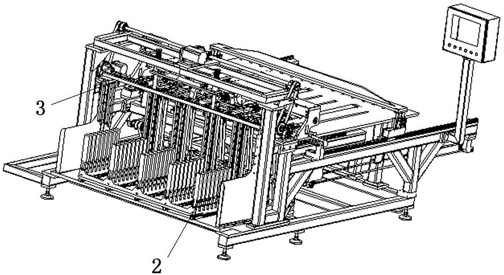
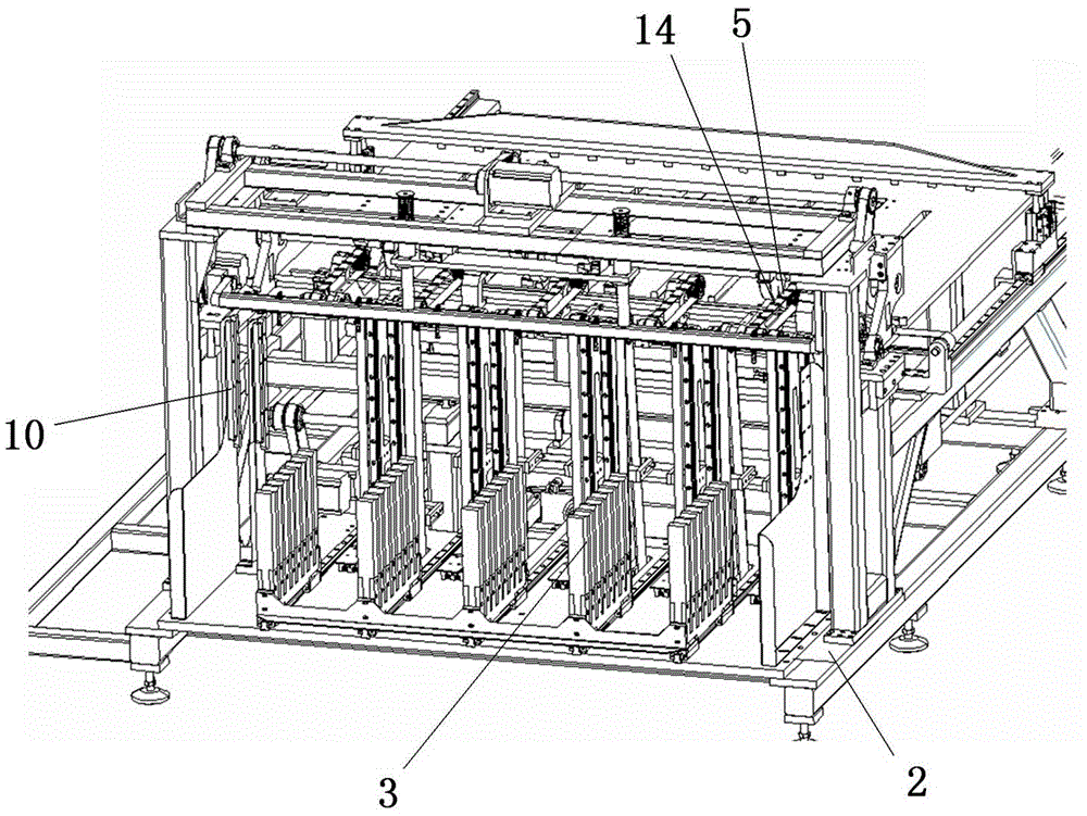
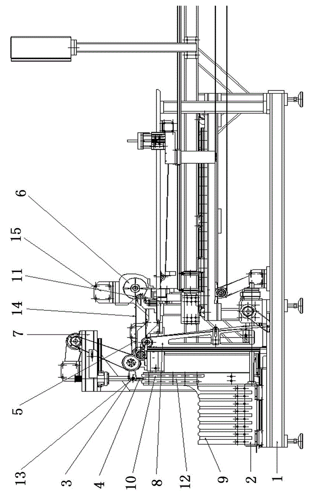
[0026] As shown in the figure, a heat exchanger flat tube conveying mechanism includes a frame 1, which is characterized in that the flat tube placement base 2 is installed on the frame 1 through a lifting device. During the assembly process, the flat tube is from bottom to top Feeding in sequence, the flat tube transfer mechanism 3 is arranged above the flat tube placement base 2, a vacuum suction cup 4 is arranged on the flat tube transfer mechanism 3, and a flat tube transmission belt 5 matching it is arranged behind the flat tube transfer mechanism 3, and the flat tube The rear portion of the transmission belt 5 is provided with a flat tube assembly turntable 6 matched with the flat tube transmission belt.

[0027] As shown in the figure, the frame 1 is provided with a gantry 7, and the lower front side of the gantry 7 is prov...


PUM


Abstract

The invention discloses a flat tube conveying mechanism in the assembly process of a micro-channel heat exchanger core. The flat tube conveying mechanism comprises a rack and is characterized in that a flat tube placing base is installed on the rack through a lifting device, flat tube transferring mechanisms are arranged above the flat tube placing base, vacuum suction cups are arranged on the flat tube transferring mechanisms, flat tube conveying belts matched with the flat tube transferring mechanisms are arranged behind the flat tube transferring mechanisms, and flat tube assembly rotating discs matched with the flat tube conveying belts are arranged at the rears of the flat tube conveying belts. The flat tube conveying mechanism has the advantages that the structure is simple and reliable, efficiency is high, the mechanization and automation degree is high, flat tube deformation and contact between flat tubes and other hard substances (such as steel) are avoided to the maximum degree, damage to the flat tubes by mutual friction between the flat tubes is avoided to the maximum degree, and the damage is definitely not allowed for the high-quality micro-channel heat exchanger core.

Description

technical field [0001] The invention relates to a material conveying mechanism, in particular to a flat tube conveying mechanism in the assembly process of a heat exchanger core. Background technique [0002] In the prior art, heat exchangers are mostly used in some special industrial equipment. During production, wavy cooling fins are placed between flat tubes for combined installation. Since the flat tubes are very thin and made of aluminum alloy, It is very soft and the surface is easy to scratch, so the flat tube heat exchanger was installed manually in the past, but the manual installation has the disadvantage of low efficiency. Now there are some equipment that use mechanical devices for automatic assembly, mainly using mechanical claws to grab the flat tubes of the heat exchanger core and assemble the heat exchanger core, but the existing equipment is to stack the flat tubes On the installation frame, use a mechanical device to push out a flat tube stacked on the bot...

Claims


Application Information

Patent Timeline
Patent Type & Authority Applications(China)
IPC IPC(8): B65G47/91B65G47/04B65G47/34B65G15/44
Inventor 宋幸长马作标
Owner 浙江其承自动化设备有限公司
Why Eureka
Try Eureka