Electrically operated valve

A technology of electric valve and valve seat, which is applied in the direction of valve lift, valve device, valve details, etc. It can solve the problems of complex configuration and structure of rectification components, reduction of refrigerant flow loss, etc., and achieves reduction of abnormal sound and simple configuration structure , the effect of suppressing flow loss

Active Publication Date: 2015-09-30
FUJIKOKI MFG CO LTD
View PDF11 Cites 7 Cited by
  • Summary
  • Abstract
  • Description
  • Claims
  • Application Information

AI Technical Summary

Problems solved by technology

[0011] However, in the conventional technology disclosed in Patent Document 2, the refrigerant flowing in from the first pipe flows back into the space formed by the main body and the rectifying member, and flows into the space having the valve body through the plurality of through holes formed in the rectifying member. , and flow to the second pipe through the throttle formed by the valve element and the valve seat, thereby suppressing the vibration of the valve element and the housing caused by the uneven state of the refrigerant and reducing noise However, there are also problems that the flow loss of the refrigerant becomes large, and the arrangement structure of the rectifying member becomes complicated.
[0012] In addition, in the conventional technology disclosed in Patent Document 3, the refrigerant is rectified when it passes through the porous body, and even when it flows into a gas-liquid two-phase flow in which the flow sound of the refrigerant is the most prominent, since the gas-liquid two-phase flow is uniform In this homogenized state, the pressure is decompressed, so the discontinuous sound is reduced and the noise reduction effect is obtained. However, the problem of increasing the flow loss of the refrigerant and the need for the porous body to act as a valve seat role problem

Method used


Image

  • Electrically operated valve
  • Electrically operated valve
  • Electrically operated valve

Examples


no. 1 Embodiment approach

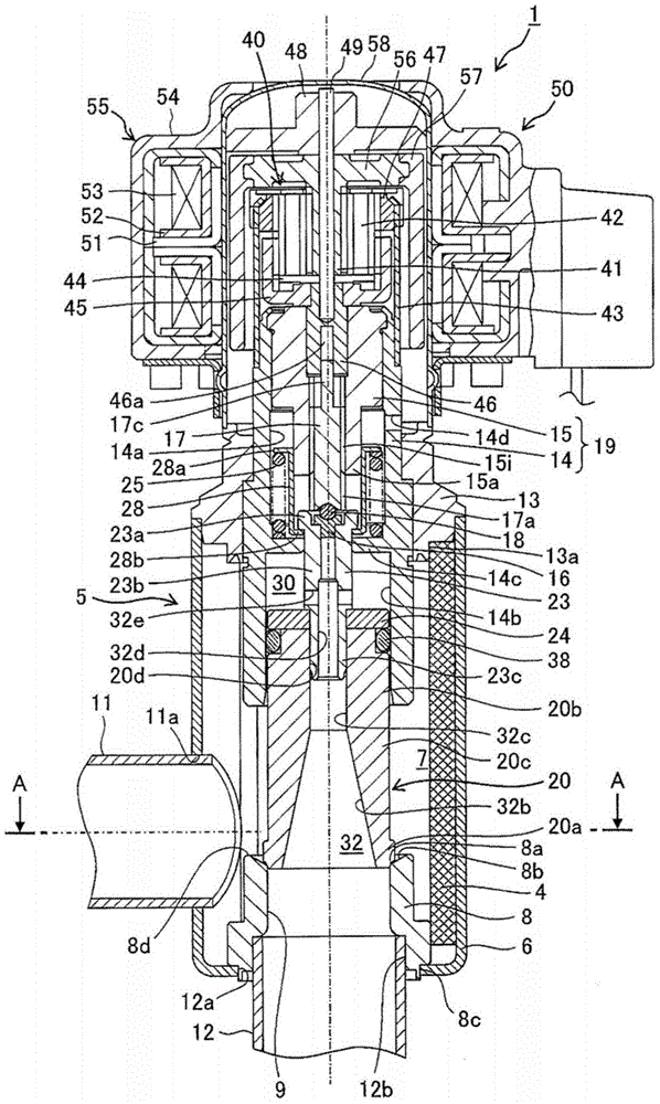
[0066] figure 1 It is a longitudinal sectional view of the first embodiment of the electric valve of the present invention, figure 2 yes figure 1 A-A in the cross-sectional view. In addition, in figure 2 In, the spool is omitted to represent.

[0067] The electric valve 1 shown in the figure is a two-way flow electric valve: it is used as an expansion valve in heat pump refrigeration and heating systems, etc., and the fluid (refrigerant) flows in two directions (the first flow direction and the second flow direction opposite to it). Flow direction) flow, and at least one direction corresponds to a flow channel with a large flow rate.

[0068] The electric valve 1 mainly has: a valve main body 5, which has a cylindrical substrate 6 made of sheet metal; a housing 58, which is fixed on the valve main body 5; a supporting member 19, which is supported by the valve main body. 5 and the internal space divided by the housing 58 is fixed on the valve main body 5; the valve co...

no. 2 Embodiment approach

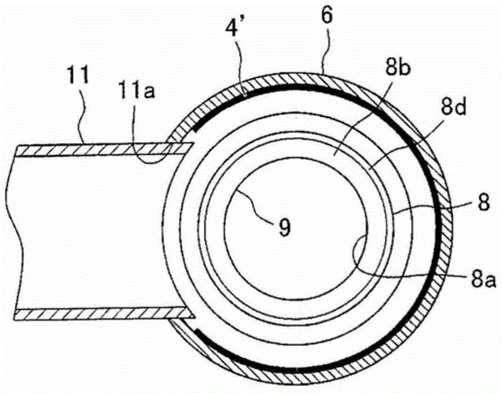
[0091] Figure 4 It is a cross-sectional view showing a second embodiment of the electric valve of the present invention. The electric valve of the second embodiment differs from the electric valve of the above-mentioned first embodiment in the shape of the porous body made of foamed metal, and the other structures are basically the same as those of the electric valve 1 of the first embodiment. Therefore, the same reference numerals are assigned to the same structures as those of the electric valve of the first embodiment, and detailed description thereof will be omitted.

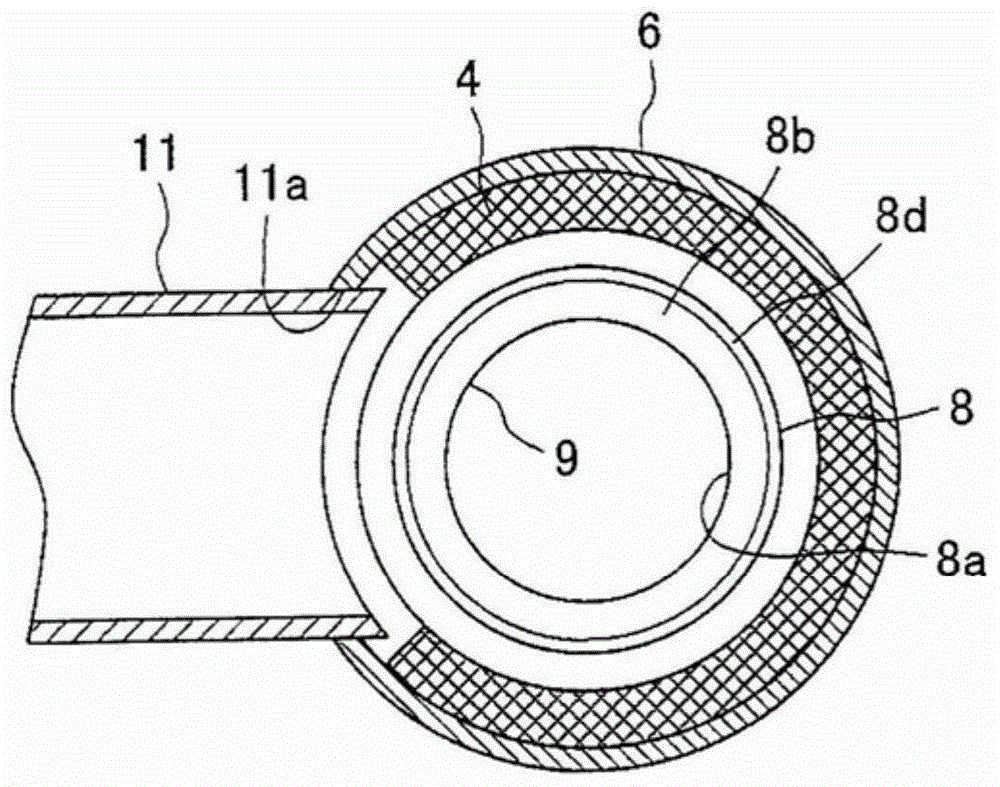
[0092] When the gas refrigerant flows in the second flow direction in a state of excessive gas, it has been confirmed by experiments by the inventors of the present invention that the valve port 9A on the side opposite to the first opening 11aA In the region between the portion and the inner wall surface of the valve main body 5A, the above-mentioned periodic vortex flow is generated in the region close to...


PUM


Abstract

The invention provides an electrically operated valve which can reduce an abnormal noise generated in the case that a fluid is flows in a first flowing direction and a second flowing direction, while suppressing a flow rate loss of a fluid with a simple structure. An electrically operated valve is provided with a valve main body (5) in which a valve chamber (7) is defined in an inner portion and a first opening (11a) and a second opening (12a) are formed in a side portion and a bottom portion, a valve seat member (8) which has an valve port (9) open to the valve chamber (7) and a valve seat (8a) and is provided in the second opening (12a) of the valve main body (5), a valve body (20) which is arranged in the valve chamber (7) so as to be movable up and down, and an elevation drive portion (50) which moves up and down the valve body (20) in relation to the valve seat (8a), and a porous body (4) constructed by a foam metal is arranged along a portion which is positioned in a side portion of the valve port on the inner wall surface of the valve main body (5).

Description

technical field [0001] The invention relates to an electric valve, in particular to an electric valve used in heat pump cooling and heating systems. Background technique [0002] For a long time, we have continuously developed electric valves for the purpose of miniaturization, increase in capacity and energy saving. As an example of such a conventional electric valve, Patent Document 1 discloses a technique of reducing the force acting in the valve closing direction as much as possible so that a valve opening spring with a smaller spring load can be used. [0003] The electric valve disclosed in Patent Document 1 has: a valve main body having a valve chamber, a first lateral port opening to the valve chamber, a longitudinal valve port with a valve seat opening to the valve chamber, And the second inlet and outlet connected with the valve port; the valve core, the valve core is configured to be liftable in the valve chamber to open and close the valve port; the lifting driv...

Claims


Application Information

Patent Timeline
Patent Type & Authority Applications(China)
IPC IPC(8): F16K47/02F16K47/08F16K1/36F16K27/02F25B41/06
CPCF25B2500/12F25B2341/061F25B41/062F25B2341/0653F25B41/38F25B41/35F16K47/02Y10T137/86759Y02B30/70F16K31/02
Inventor 原田贵雄田渊健资延木武德
Owner FUJIKOKI MFG CO LTD
Why Eureka
Try Eureka