Thermal resistance analysis method

An analysis method and thermal resistance technology, applied in the field of device thermal characteristics measurement, can solve the problems of serious air convection, increase the volume of static air test box, and large volume, achieve a wide range of applications, shorten thermal resistance analysis time, and ensure accurate degree of effect

Active Publication Date: 2015-09-30
HANGZHOU EVERFINE PHOTO E INFO
View PDF7 Cites 6 Cited by
  • Summary
  • Abstract
  • Description
  • Claims
  • Application Information

AI Technical Summary

Problems solved by technology

However, the existing literature does not give the specific corresponding relationship between power and the volume of the test chamber, and it is difficult to realize the actual operation; secondly, due to the limitation of the size of the test equipment, it is impossible to increase the volume of the static air test chamber infinitely
For example, for devices less than 3W, the volume of the static air test chamber is generally 0.0283m 3 (a cube with a side length of 30.48cm); when measuring a 100W COB, even if it is increased in the same proportion, the volume of the static air test chamber needs to be about 27m 3 (a cube with a side length of 3m) is even larger. On the one hand, such a large-volume box has serious air convection and cannot meet the requirements of a static air environment; on the other hand, the static air test box plus other supporting equipment, the entire The volume of the test system is huge, and the thermal equilibrium time is also long, which is generally difficult for users to accept

Method used


Image

  • Thermal resistance analysis method
  • Thermal resistance analysis method
  • Thermal resistance analysis method

Examples


Embodiment 1

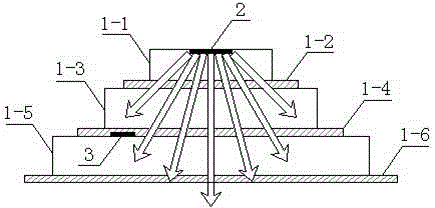
[0030] This embodiment discloses a thermal resistance analysis method. The test object of this embodiment is a high-power device 1 including a six-layer structure, which is respectively recorded as the first layer 1-1, the second layer 1-2, and the third layer. 1-3, the fourth floor 1-4, the fifth floor 1-5 and the sixth floor 1-6, such as figure 1 The material parameters are shown in Table 1.

[0031] The parameters of the six-layer structure of the high-power device in Table 1 Example 1

[0032] A=1mm 2 λ[W / m.k] ρ[g / cm 3 ] c[J / gK] d[mm] R[K / W] C[J / K] 1-1 148 2.33 0.7 0.2 1.351 3.262×10 -4

[0033] 1-2 1.6 3.8 0.48 0.05 31.25 9.12×10 -5 1-3 350 8.89 0.385 1 2.85714 3.423×10 -3 1-4 0.73 2.8 1 0.03 41.0959 8.4×10 -5 1-5 180 27 0.963 1 5.5556 0.026 1-6 0.18 1.18 1.424 0.05 277.78 8.4016×10 -5

[0034] The heat source 2 of the high-power device 1 is located at the first layer 1...

Embodiment 2

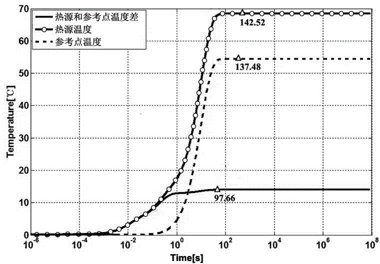
[0040] This embodiment discloses a thermal resistance analysis method in which the temperature of the heat source and the reference point are both stable. Similar to Embodiment 1, the test object of this embodiment is also a high-power device 1 including a six-layer structure, which is respectively recorded as the first layer 1-1, the second layer 1-2, the third layer 1-3, the fourth layer 1-4, the fifth layer 1-5 and the sixth layer 1-6, different from embodiment 1, the first layer of this embodiment The material parameters of the six layers are different from those in Example 1, and their material parameters are shown in Table 3.

[0041] Table 3 The parameters of the six-layer structure of the high-power device in Example 2

[0042] A=1mm 2 λ[W / m.k] ρ[g / cm 3 ] c[J / gK] d[mm] R[K / W] C[J / K] 1 148 2.33 0.7 0.2 1.351 3.262×10 -4 2 1.6 3.8 0.48 0.05 31.25 9.12×10 -5 3 350 8.89 0.385 1 2.85714 3.423×10 -3 4 0.73 2.8 1...


PUM


Abstract

The invention discloses a thermal resistance analysis method. The method comprises the following steps: synchronously monitoring the heat source temperature and reference point temperature of a high-power device, and introducing a quasi-thermal balance state judgment method with stable heat source and reference point temperature difference, so that accurate analysis of the thermal resistance information in a customized area of the high-power device can be realized, the reference point position can be accurately customized, and the resolution rate of the thermal resistance structure is effectively improved. The thermal resistance analysis method can be widely applied to accurate measurement of thermal characteristic tests of various high-power devices and has the characteristics of high efficiency, rapidness, wide application range and the like.

Description

【Technical field】 [0001] The invention belongs to the field of device thermal characteristic measurement, and in particular relates to a thermal resistance analysis method. 【Background technique】 [0002] The thermal characteristics of the device are generally measured under the condition that the ambient temperature does not change significantly. During the test, the device is required to reach a thermal equilibrium state and the ambient temperature in the box does not change significantly. For example, the device under test is placed in a static air test chamber. Low-power devices are easier to achieve the above test conditions, but for high-power devices (such as high-power LEDs, etc.), even if they can reach thermal balance, due to their large heat dissipation, the ambient temperature rises or falls significantly during the test. Air cannot be regarded as an infinite heat sink, and the temperature change in this part will be intuitively reflected in the thermal resistanc...

Claims


Application Information

Patent Timeline
Patent Type & Authority Applications(China)
IPC IPC(8): G01N25/20
Inventor 潘建根陈聪李晟
Owner HANGZHOU EVERFINE PHOTO E INFO
Why Eureka
Try Eureka