Wideband variable-temperature dielectric constant testing system for solid and powder materials

A powder material and dielectric constant technology, applied in the microwave field, can solve the problems of high requirements, low test accuracy, complicated operation, etc., and achieve the effect of easy calibration, simple operation, and improved test accuracy.

Active Publication Date: 2015-09-30
UNIV OF ELECTRONIC SCI & TECH OF CHINA
View PDF9 Cites 7 Cited by
  • Summary
  • Abstract
  • Description
  • Claims
  • Application Information

AI Technical Summary

Problems solved by technology

Among them, the free space method is not suitable for the measurement of powder materials; the coaxial probe method has high requirements on the sample material, and the sample to be tested needs to be smooth and flat, and the probe should be in close contact with the material to be tested;

Method used


Image

  • Wideband variable-temperature dielectric constant testing system for solid and powder materials
  • Wideband variable-temperature dielectric constant testing system for solid and powder materials
  • Wideband variable-temperature dielectric constant testing system for solid and powder materials

Examples


Embodiment

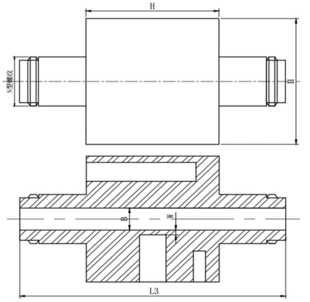
[0039] In this embodiment, the test system designed by the present invention is designed according to the radio frequency 50 ohm impedance matching design, reduces reflection, and is used in conjunction with the microwave measurement system, and has good matching. Secondly, in this embodiment, the connectors of the test system designed by the present invention refer to the N-type radio frequency coaxial connector, and the size of the part where the heating rod and temperature sensor are placed in the middle is HxH. The specific size can be based on the heating rod and Temperature sensor adjustment. The specific design is described in detail below:

[0040] The broadband variable temperature dielectric constant test system for solid and powder materials of the present invention includes:

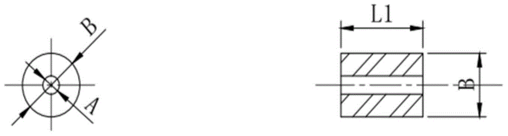
[0041] The measured solid material, such as figure 1 As shown, the inner circle through hole diameter is A=2mm, the outer ring diameter is B=7mm, and the length is L1=10mm.

[0042] Do not process...


PUM

PropertyMeasurementUnit
Diameteraaaaaaaaaa

Abstract

The invention discloses a wideband variable-temperature dielectric constant testing system for solid and powder materials. The wideband variable-temperature dielectric constant testing system has the advantages that complex dielectric constants of the solid and powder materials can be tested on the basis of transmission and reflection methods under variable-temperature conditions; testing fixtures and Thru, Reflect and Line calibrating devices matched with the testing fixtures are designed, the testing fixtures, the Thru, Reflect and Line calibrating devices are used with temperature controllers, temperature sensors and heating rods during particular tests, and accordingly the complex dielectric constants of solid and powder can be tested under the wideband variable-temperature conditions.

Description


Claims


Application Information

Patent Timeline
Owner UNIV OF ELECTRONIC SCI & TECH OF CHINA
Why Eureka
Try Eureka