Groove processing tool and scoring device with same

A technology for processing tools and grooves, applied in the field of scribing devices, can solve the problems of deterioration of cutting ability, insufficient insulation effect, narrow processing groove width, etc., and achieve the effect of preventing deterioration of cutting ability

Active Publication Date: 2015-09-30
MITSUBOSHI DIAMOND IND CO LTD
View PDF7 Cites 0 Cited by
  • Summary
  • Abstract
  • Description
  • Claims
  • Application Information

AI Technical Summary

Problems solved by technology

[0016] However, once the blade tip of the grooving tool is used while pressing the thin-film solar cell with the above-mentioned pressing force, the corners 30 and 32 of the blade tip corresponding to the outer peripheral side surface and the bottom surface of the groove processing depth h are different from each other. When the films of the solar cell substrate come into contact with each other, wear occurs from the new product state in Fig. 9(a), and as shown in Fig. 9(b), the left and right width of the blade tip becomes smaller and the cutting ability deteriorates
Once the left and right width of the front end of the blade becomes smaller, the width of the groove to be processed becomes narrow, making it impossible to process a groove of a specified size with high precision, and it also occurs in the Figure 7(a) ~ Figure 7(c) When the trenches P2 and P3 for electrode separation cannot obtain sufficient insulating effect
In addition, if the cutting ability of the tip of the blade deteriorates, not only the grooves cannot be processed beautifully, but also a part of the film may be irregularly peeled off more than necessary, and the characteristics and yield of the solar cell may decrease. question

Method used


Image

  • Groove processing tool and scoring device with same
  • Groove processing tool and scoring device with same
  • Groove processing tool and scoring device with same

Examples


Embodiment Construction

[0043] Hereinafter, the details of the present invention will be described in detail based on drawings showing embodiments thereof.

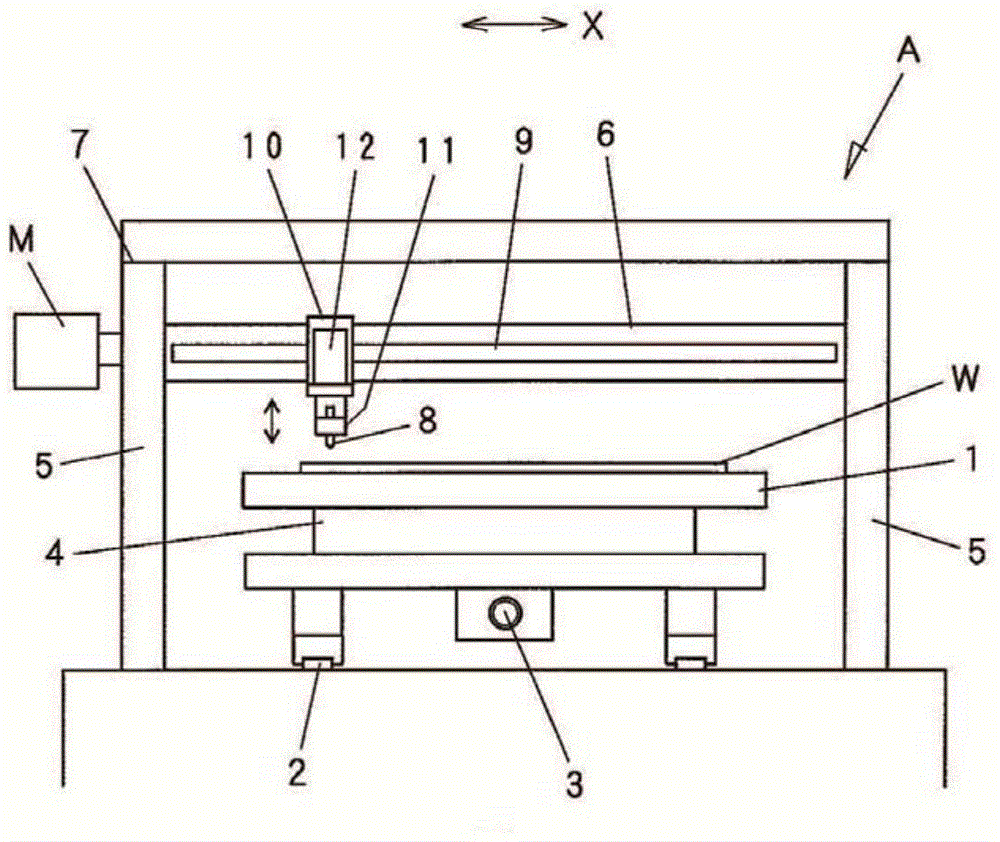
[0044] figure 1 It is a schematic front view showing an example of a scribing apparatus for a build-up type thin-film solar cell using the trenching tool of the present invention.

[0045] The scribing apparatus A includes a table 1 on which a solar cell substrate W is placed and held. The platform 1 becomes able to move along the horizontal rail 2 in the Y direction ( figure 1 front and rear directions) and is driven by a screw shaft 3 that is rotated by a motor (not shown). Furthermore, the platform 1 can be rotated in a horizontal plane by the rotation drive part 4 with a built-in motor.

[0046] A bridge frame 7 including support columns 5 and 5 on both sides provided across the platform 1 and beams (beams) 6 extending horizontally in the X direction is installed so as to straddle the platform 1 .

[0047] The beam 6 is provided with a...


PUM


Abstract

The invention relates to a groove processing tool and a scoring device provided with the groove processing tool. The groove processing tool is provided with a clubbed body 81, a taper conical portion 82 formed on the lower part of the body 81, and a blade front end region 84 which is formed on the front end of the conical portion 82 or the front end of a cylinder portion 83, the cylinder portion 83 being formed by connecting with the conical portion 82. The blade front end region 84 is formed by a horizontal bottom surface 85, and a blade front end 87 which is formed by the bottom surface 85, and corner portions of the peripheral side surface 86 of the cylinder portion 83 or the conical portion 82. A coating film of the peripheral side surface 86 is a film made of a hard material which is harder than the material of the tool. The bottom surface 85 exposes the texture of the tool material. The technical scheme can improve wear resistance, prolong service life, and restrain film from stripping in groove processing through processing the shape of the front end of the blade.

Description

technical field [0001] The present invention relates to a groove processing tool used in the manufacture of an integrated thin film solar cell using a compound such as chalcopyrite or cadmium telluride, and a device equipped with the groove processing tool Scoring device. [0002] Here, the so-called chalcopyrite compounds, except CIGS(Cu(In,Ga)Se 2 ), including CIGSS (Cu(In,Ga)(Se,S) 2 ), CIS (CuInS 2 )Wait. Background technique [0003] A thin-film solar cell using a compound semiconductor as a light-absorbing layer generally has an integrated structure in which a plurality of unit cells are connected in series on a substrate. [0004] A method for producing a conventional chalcopyrite compound integrated thin-film solar cell will be described. Figure 7(a) ~ Figure 7(c) It is a schematic diagram showing the manufacturing steps of a CIGS thin film solar cell. First, as shown in FIG. 7( a ), on an insulating substrate 21 made of soda-lime glass (SLG) or the like, Mo ( ...

Claims


Application Information

Patent Timeline
Patent Type & Authority Applications(China)
IPC IPC(8): H01L31/18
CPCY02P70/50
Inventor 广野嘉文
Owner MITSUBOSHI DIAMOND IND CO LTD
Why Eureka
Try Eureka