Three-terminal isolation type ES (electric spring) topological structure and control method thereof

A technology of electric spring and topological structure, which is applied in the field of three-terminal isolated electric spring topological structure and its control, can solve the problems of uneconomical and unfavorable promotion of new energy power generation, and achieve the effect of increasing safety

Inactive Publication Date: 2015-09-30
SOUTHEAST UNIV
View PDF2 Cites 14 Cited by
  • Summary
  • Abstract
  • Description
  • Claims
  • Application Information

AI Technical Summary

Problems solved by technology

Obviously, such a method is neither economical nor conduc

Method used


Image

  • Three-terminal isolation type ES (electric spring) topological structure and control method thereof
  • Three-terminal isolation type ES (electric spring) topological structure and control method thereof
  • Three-terminal isolation type ES (electric spring) topological structure and control method thereof

Examples


Example Embodiment

[0033]The present invention will be further explained below in conjunction with the accompanying drawings.
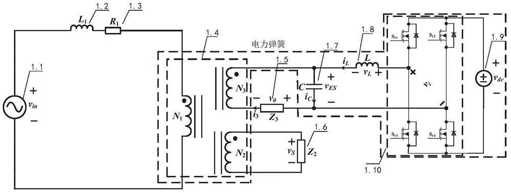
[0034] like figure 1 As shown, a three-terminal isolated power spring topology structure includes a single-phase voltage source inverter, an LC low-pass filter, and a single-phase three-port isolation transformer. The transformation ratio of the single-phase three-port isolation transformer is 1:1:1. The DC side of the single-phase voltage source inverter is connected to the DC power supply, the positive output end of the single-phase voltage source inverter is connected to one end of the filter inductor L of the LC low-pass filter, and the other end of the filter inductor L is connected to the filter capacitor C at the same time. One end of the single-phase three-port isolation transformer and the first winding N of the secondary side of the single-phase three-port isolation transformer 3 The other end of the filter capacitor C is connected to the negative output end...


PUM


Abstract

The invention discloses a three-terminal isolation type ES (electric spring) topological structure and a control method thereof. A power grid, a critical load and a non-critical load can be effectively isolated, the structure provides security assurance and plays a key promotion role for wide application of an ES to a distributed power generation system, the topological structure is applied to the distributed power generation system and is particularly applicable to small wind power generation and photovoltaic power generation grid-connected systems in residential areas, and fluctuation effects caused by intermittence of new energy resources on power grid voltage can be eliminated from the source. The topological structure can be used as an existing topological structure to transfer fluctuation of input voltage to the non-critical load, help a common user to distribute electric energy of the critical load independently and transmit redundant power to the power grid while meeting the power demand of the topological structure.

Description

technical field [0001] The invention belongs to the technical field of smart grid control, and relates to a three-terminal isolation electric spring topology and a control method thereof. Background technique [0002] The traditional operation mode of the power system is still that the demand determines the power supply, which requires the power company to accurately predict the user's demand. Due to the intermittency and instability of renewable energy such as wind energy and solar energy, and with the gradual increase of its power generation and grid-connected capacity, the difficulty of the above prediction is gradually increasing, and the impact on the power system is becoming more and more obvious. For the interstitial problem of renewable energy, using energy storage devices to offset the mismatch between power generation and power consumption is one of the effective solutions. However, these energy storage devices increase the cost. [0003] The concept of electric ...

Claims


Application Information

Patent Timeline
IPC IPC(8): H02J3/00H02J3/04H02J3/38
Inventor 程明王青松
Owner SOUTHEAST UNIV
Why Eureka
Try Eureka