
Radial ventilation cooling structure of motor

A technology of cooling structure and radial ventilation, applied in the direction of cooling/ventilation device, magnetic circuit shape/style/structure, electromechanical device, etc., can solve the problems of small air velocity, thermal deformation of iron core support, large maximum temperature value, etc., to achieve Avoid downtime, ensure normal operation, and improve the effect of balance

Active Publication Date: 2015-09-30
BEIJING GOLDWIND SCI & CREATION WINDPOWER EQUIP CO LTD
View PDF8 Cites 35 Cited by
  • Summary
  • Abstract
  • Description
  • Claims
  • Application Information

AI Technical Summary

Problems solved by technology

[0004] In the process of realizing the above-mentioned ventilation and cooling, the inventors found that there are at least the following problems in the prior art: after the airflow enters the air gap, the speed of the airflow becomes smaller and smaller due to the diversion of the ventilation ditch, local and along-the-way resistance, etc. In this way, from the entrance of the air gap to the middle position of the air gap, the static pressure is getting larger and the dynamic pressure is getting smaller and smaller.
The temperature of the coil and multiple core segments is unevenly distributed along the motor axis, and the maximum temperature value is relatively large, which is prone to excessive local temperature rise, resulting in motor shutdown and failure, and at the same time easily causing thermal deformation of the core bracket, affecting the normal operation of the motor

Method used


Image

  • Radial ventilation cooling structure of motor
  • Radial ventilation cooling structure of motor
  • Radial ventilation cooling structure of motor

Examples


Embodiment 1

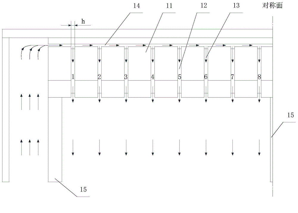
[0038] refer to figure 1 As shown in the existing motor radial ventilation cooling structure, the motor radial ventilation cooling structure of the embodiment of the present invention also includes at least three iron core segments 11, and ventilation channel steel 12 is arranged between adjacent iron core segments 11, adjacent A ventilation groove 13 is formed between the iron core segment 11 and the ventilation channel steel 12, but different from the existing motor radial ventilation cooling structure, due to the different structures of the multiple ventilation channel steels 12 and / or the multiple core segments 11, As a result, the impedance R of the plurality of ventilation grooves 13 gradually increases along the direction from both ends of the motor to the middle of the motor.

[0039] Specifically, the resistance R of the ventilation groove 13 is the resistance of the ventilation groove 13 to the airflow (including local resistance and along-way resistance). The venti...

Embodiment 2

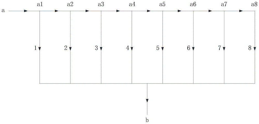
[0045] refer to figure 1 As shown in the existing motor radial ventilation cooling structure, the motor radial ventilation cooling structure of the embodiment of the present invention also includes at least three iron core segments 11, and ventilation channel steel 12 is arranged between adjacent iron core segments 11, adjacent A ventilation groove 13 is formed between the iron core segment 11 and the ventilation channel steel 12, but different from the existing motor radial ventilation cooling structure, due to the different structures of the multiple ventilation channel steels 12 and / or the multiple core segments 11, As a result, the impedance R of the plurality of ventilation grooves 13 gradually increases along the direction from both ends of the motor to the middle of the motor, and the impedance S of the ventilation paths where the plurality of ventilation grooves 13 are located is equal. Wherein, the impedance S of the ventilation path is equal to the sum of the impedan...

Embodiment 3

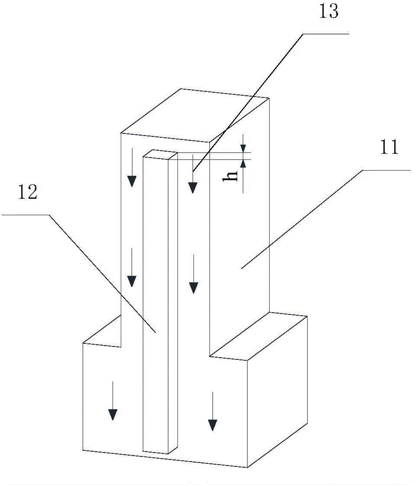
[0051] Figure 4 Schematic diagram of the adjusted size of the ventilation channel steel in one embodiment of the motor radial ventilation cooling structure provided by the present invention, Figure 5 for Figure 4 The schematic diagram of the structure of the ventilation channel steel in the radial ventilation cooling structure of the motor shown. Such as Figure 4 , Figure 5 As shown, on the basis of Embodiment 1 or Embodiment 2, the radial ventilation and cooling structure of the motor in this embodiment provides that by adjusting the size of the ventilation channel steel 12 (including the height h in the axial direction of the motor and / or The width w) in the circumferential direction of the motor makes the impedance R of the plurality of ventilation grooves 13 gradually increase along the direction from both ends of the motor to the middle of the motor.

[0052] Specifically, the ventilation channel steel 12 in this embodiment is still an overall in-line strip-shape...


PUM


Abstract

The invention provides a radial ventilation cooling structure of a motor. The radial ventilation cooling structure for the motor comprises at least three iron core sections, wherein ventilation channel steel is arranged between every two adjacent iron core sections; a ventilating duct is formed between every two adjacent iron core sections and the ventilation channel steel; the impedance of the multiple ventilating ducts is gradually increased along two ends of the motor to the middle direction of the motor. According to the radial ventilation cooling structure of the motor, provided by the invention, the impedance of the multiple ventilating ducts is gradually increased along the two ends of the motor to the middle direction of the motor, so that the balance of the flow of wind flowing through the multiple ventilating ducts can be improved, and further the balance that the temperatures, along the axial direction of the motor, of a coil and the multiple iron core sections are distributed is improved; under the condition that total flow of the wind is unchanged, a maximum temperature value is reduced, and motor shutdown caused by overhigh local temperature rising is effectively avoided; meanwhile, thermal deformation of an iron core bracket is reduced, and normal operation of the motor is guaranteed.

Description

technical field [0001] The invention relates to the technical field of motors, in particular to a motor radial ventilation cooling structure. Background technique [0002] When the motor (including motors and generators) is running, energy loss will occur on components such as coils and iron cores, and this part of the loss will eventually be dissipated in the form of heat energy. Radial ventilation cooling is one of the commonly used cooling methods for motors. This cooling method can increase the heat dissipation area and improve the power density of the generator, so it has been widely used. [0003] figure 1 It is a structural schematic diagram of an existing motor radial ventilation cooling structure. Such as figure 1 As shown (only half of the symmetrical structure of the motor is shown), the core (stator or rotor core) of the motor is divided into a plurality of core segments 11, and ventilation slots are arranged between adjacent core segments 11 along the radial ...

Claims


Application Information

Patent Timeline
IPC IPC(8): H02K9/18
CPCH02K1/20H02K1/32H02K2205/12H02K2213/03H02K2213/09H02K5/02H02K9/10H02K9/16
Inventor 范文寿马盛骏
Owner BEIJING GOLDWIND SCI & CREATION WINDPOWER EQUIP CO LTD
Learn More