Laser processing apparatus and laser processing method

A technology of laser processing and laser beams, which is applied in the direction of fine working devices, laser welding equipment, stone processing equipment, etc., can solve problems affecting processing accuracy and achieve the effects of energy loss suppression and simple device structure

Inactive Publication Date: 2015-09-30
V TECH CO LTD
View PDF13 Cites 6 Cited by
  • Summary
  • Abstract
  • Description
  • Claims
  • Application Information

AI Technical Summary

Problems solved by technology

According to this, giving artificial beating will greatly affect the processing accuracy, and to some extent, it is unavoidable to reduce the yield due to the occurrence of cracks.

Method used


Image

  • Laser processing apparatus and laser processing method
  • Laser processing apparatus and laser processing method
  • Laser processing apparatus and laser processing method

Examples


Embodiment Construction

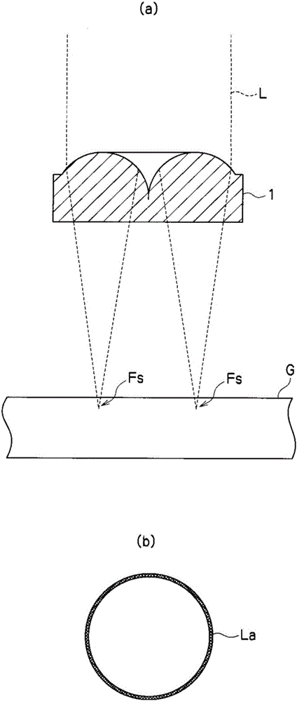
[0023] Hereinafter, a laser processing device and a laser processing method according to an embodiment of the present invention will be described with reference to the drawings. figure 1 It is an explanatory diagram showing a form example of a laser lens used in an embodiment of the present invention ( figure 1 (a) is a figure which shows the cross-sectional shape of a condensing lens and the condensing state of a laser beam, figure 1 (b) is a plan view of the beam shape of the laser beam condensed into a ring shape). The condensing lens 1 condenses the laser beam L into a ring shape and irradiates its condensing position Fs within a substantially G thickness range. The condensing lens 1 basically sets the cylindrical lens as an annular shape, and by injecting the laser beam L with a circular cross-section shaped into a predetermined beam diameter into the effective aperture, the following can be obtained: figure 1 The ring-shaped light-condensing state La shown in (b).

[...


PUM

PropertyMeasurementUnit
thicknessaaaaaaaaaa

Abstract

In the present invention, a laser beam is focused into an annular shape and irradiated on a beam-focus location within a substrate thickness range; and, in a process in which the beam-focus location is shifted in the substrate thickness direction and in the substrate planar direction, the beam-focus location is shifted so that the center of the ring-shaped beam-focus location moves in a circular manner. It is thereby possible to reduce the cost of the apparatus and the process treatment time.

Description

technical field [0001] The present invention relates to a laser processing device and a laser processing method for performing perforation processing on substrates such as glass. Background technique [0002] In recent years, glass substrates with a thickness of less than 1mm have been used for display screens of personal digital assistants such as smartphones, and holes are processed on the glass substrates to correspond to functions such as various buttons and microphones. In the hole processing of the brittle material of the glass substrate mentioned above, the fall of the yield by the generation|occurrence|production of a crack during processing becomes a problem. In particular, when the hole for the main screen button on the screen of the personal digital assistant mentioned above penetrates through a relatively large hole with a diameter of about 10mm, a circular processing crack is given on the surface by using a glass knife with a diamond blade, and further A circul...

Claims


Application Information

Patent Timeline
Patent Type & Authority Applications(China)
IPC IPC(8): B23K26/382B23K26/046B23K26/06B23K26/08B23K26/082C03B33/09B28D5/00
CPCB23K26/0734B23K26/0823G02B26/10G02B27/0927G02B27/0933G02B27/0955C03B33/0222C03B33/04C03B33/102C03C23/0025G02B7/02G02B19/0009
Inventor 水村通伸滝本政美松山将太
Owner V TECH CO LTD
Why Eureka
Try Eureka