Unlock instant, AI-driven research and patent intelligence for your innovation.

Production method and production device for fan blades

A technology of a fan blade and a manufacturing method, which is applied in the field of fan blade manufacturing and manufacturing devices, can solve the problems of long fan blade length and the like, and achieve the effect of suppressing the generation of wrinkles

Active Publication Date: 2015-09-30
IHI CORP
View PDF14 Cites 7 Cited by
  • Summary
  • Abstract
  • Description
  • Claims
  • Application Information

AI Technical Summary

Problems solved by technology

If the bypass ratio is increased, the diameter of the fan becomes larger than that of the core motor, so the length of the fan blades constituting the fan becomes longer

Method used


Image

  • Production method and production device for fan blades
  • Production method and production device for fan blades
  • Production method and production device for fan blades

Examples


Embodiment Construction

[0032] Hereinafter, preferred embodiments of the present invention will be specifically described with reference to the drawings. Dimensions, materials, and other specific numerical values ​​shown in the embodiments are merely illustrations for easy understanding of the invention, and do not limit the invention unless otherwise specified. In this specification and the drawings, components having substantially the same functions and structures are given the same reference numerals and repeated explanations are omitted, and illustration of components not directly related to the present invention is omitted.

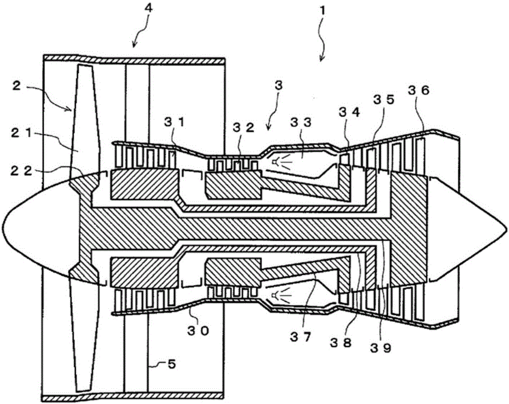
[0033] (Turbofan Engine 1)

[0034] figure 1 A schematic side sectional view showing a turbofan engine 1 with fan blades. The turbofan engine 1 is composed of a fan 2 that generates most of the thrust, and a core engine 3 that has a turbine arranged behind the fan 2 to drive the fan 2 .

[0035] The core engine 3 is composed of a turbojet engine with a low-pressure compr...


PUM


Abstract

A raw material plate (7) comprising a plurality of main fibers (71) oriented in parallel, a plurality of auxiliary fibers (72) oriented in parallel and intersecting the main fibers (71), and a resin that integrates these main fibers (71) and auxiliary fibers (72) is sandwiched by a frame-shaped blank holder (8), in a state in which the resin is heated to a temperature at which same becomes soft. The raw material plate (7) sandwiched by the blank holder (8) is pressed on to a fan blade mold (6b) such that the direction of the main fibers (71) matches the longitudinal direction (Y) of the fan blade mold (6b), thereby applying a suitable tension to the raw material plate (7) along the main fiber (71) direction, and suppressing creases.

Description

technical field [0001] The present invention relates to a manufacturing method and a manufacturing apparatus of a fan blade made of a fiber-reinforced composite material that uses a raw material plate that integrates a plurality of parallel-oriented fibers with a resin. Background technique [0002] A turbofan engine used as an engine for an aircraft is composed of a fan that generates most of the thrust, and a core engine (turbojet engine) having a turbine arranged behind the fan to drive the fan. The fan is arranged coaxially with the core engine, and the air drawn into the fan from the front of the engine is divided into a part (Gf) that is directly discharged to the rear by the fan and a part (Gc) that enters the core engine for combustion and rotates the turbine and is discharged rearward. Their ratio (Gf / Gc) is called the bypass ratio. [0003] Since fuel efficiency is better with a higher bypass ratio, turbofan engines with a higher bypass ratio have been developed i...

Claims


Application Information

Patent Timeline
Patent Type & Authority Applications(China)
IPC IPC(8): F04D29/38B29C70/06F01D25/00F02C7/00F02K3/06B29K105/08B29L31/08
CPCY02T50/672F01D5/282B29D99/0025B29L2031/082B29C70/345F05D2220/36F04D29/023F04D29/324B29C70/202Y02T50/673F05D2230/50F05D2300/6034B29C70/56Y02T50/60B29C70/541B29C70/18B29C70/467F01D5/12F04D29/388B29K2101/12B29K2105/08B29K2307/04
Inventor 村上务盛田英夫稻田贵臣八木广幸佐藤诚一马场俊一
Owner IHI CORP