Positioning structure and positioning method for casting castings

A positioning structure and positioning method technology, applied in the direction of casting molding equipment, casting molds, casting mold components, etc., can solve problems such as waste of manpower, easy collision, casting runaway, etc., to improve operating efficiency, avoid collisions, and avoid deviations The effect of box wrong type

Inactive Publication Date: 2015-10-07
刘天平
View PDF9 Cites 10 Cited by
  • Summary
  • Abstract
  • Description
  • Claims
  • Application Information

AI Technical Summary

Problems solved by technology

[0006] (1) The matching accuracy of the sand box pin sleeve is high, and the processing cost of casting equipment is high;
[0007] (2) The matching precision of the sand box pin sleeves is high, and the gap between the pin sleeves is small. The straightness and stability of the manual operation of boxing and closing are high, and skilled workers are required to operate freely; at the same time, the operating efficiency is low;
[0010] (1) The upper and lower molds with convex-convex or curved surface are easy to collide when they are combined, resulting in sand falling and fleshy castings, resulting in defective products;
[0011] (2) When the box is closed, if the mold has its own positioning boss or positioning concave table and hits the sand, the box will appear partial and cause the wrong shape of the casting;
[0012] (3) If the casting mold has its own positioning boss or positioning concave table and hits the sand when the box is closed, sometimes the knocked-off sand block will also affect the box combination due to the cushion box, and the casting will run out of fire and cause the entire casting to fail;
[0013] (4) Since the closing only depends on the positioning boss or positioning concave of the casting mold, and it must be within the effective height of the positioning convex or positioning concave to play a positioning role, the closing generally requires multiple people to operate at the same time, and the closing It is also cautious from top to bottom, which wastes manpower and inefficiencies

Method used


Image

  • Positioning structure and positioning method for casting castings
  • Positioning structure and positioning method for casting castings
  • Positioning structure and positioning method for casting castings

Examples


Embodiment Construction

[0036] The following combination Figure 1-Figure 13 Specific embodiments of the present invention will be described in detail.

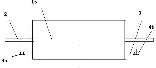
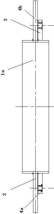
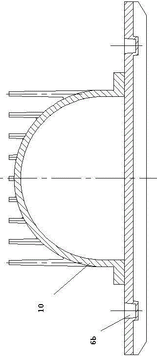
[0037] In the implementation process of the present invention, at first need to manufacture the upper mold and lower mold of mould, then utilize upper mold to form upper sand mold in upper sand box, utilize lower mold to form lower sand mold in lower sand box, then utilize upper mold and lower sand box The sand box is closed. After the box is closed, the molten liquid is poured from the sand gate into the gap formed by the sand mold. After cooling, the sand mold space will form a casting. The concave-convex shape in the above mold is consistent with the concave-convex shape in the sand box, and the direction is opposite. The positioning concave platform (boss) will be formed in the sand box. The positioning concave platform and the positioning convex platform in the sand box are matched with each other after the box is closed. In the following desc...


PUM


Abstract

The invention discloses a positioning structure and a positioning method for casting castings, and belongs to the field of casting. Moulding flasks comprise an upper moulding flask and a lower moulding flask, wherein flask lugs are arranged on the moulding flasks; a pin bush or a positioning pin is arranged on each flask lug; dies comprise an upper die and a lower die; the upper die and the lower die are respectively arranged on base plates; positioning pins or pin bushes are arranged on the base plates of the dies; the pin bushes or positioning pins on the moulding flasks are matched with the corresponding positioning pins or pin bushes of the dies; long-stroke bolts are arranged on the moulding flasks; a positioning convex platform or positioning concave platform is arranged on each die. According to the positioning structure and the positioning method disclosed by the invention, the collision generated when the upper moulding flask and the lower moulding flask are closed, waste and defective products caused by shakeout and excessive metal, and the castings shift caused by flask deviation after the collision of the moulding flasks are avoided, the condition that the closing of the moulding flasks is influenced by flask packing of flask lumps is eliminated, the casting failure phenomenon caused by casting runout is avoided, the labor cost is reduced, and the rate of finished products is improved.

Description

technical field [0001] The invention relates to a positioning structure and a positioning method, in particular to a positioning structure and a positioning method in casting casting, and belongs to the field of casting. Background technique [0002] The formation of castings is first to use metal molds and wood to form the same appearance and sand core as the casting, and then use the molding sand, the pattern in combination with the gate and riser system in the sand box to form a mold. The mold is generally made of molding sand. sand mold, the outer periphery of the sand mold is a sand box, and the upper box includes an upper sand box and a lower sand box, in which the upper sand mold and the lower sand mold are formed respectively. The cavity of the casting is formed between the boxes, and the casting melt is injected into the cavity, and the casting is formed after cooling. [0003] Among them, molding sand molding sand is generally made by mixing molding materials such...

Claims


Application Information

Patent Timeline
Patent Type & Authority Applications(China)
IPC IPC(8): B22C21/10B22C9/20
Inventor 刘天平王爱丽
Owner 刘天平
Why Eureka
Try Eureka