Full-automatic glass panel printing machine

A glass panel and printing machine technology, applied to printing machines, rotary printing machines, screen printing machines, etc., can solve the problems of limited input costs, damage to the interests of personnel and manufacturers, and limit the production efficiency of enterprises, so as to achieve a simple and hot overall structure. Compactness, reduced position adjustment range, and the effect of avoiding printing defects

Inactive Publication Date: 2015-10-07
DONGGUAN RBD TECH
View PDF6 Cites 21 Cited by
  • Summary
  • Abstract
  • Description
  • Claims
  • Application Information

AI Technical Summary

Problems solved by technology

[0002] Modern production is already an era of automated production, but many manufacturers have to use a lot of manual work due to limited input costs
In the current glass production field, glass printing equipment is an important process of glass processing. Many manufacturers still use manual delivery as the carrier. Although the existing glass printing equipment has a high degree of automation, it still lacks supporting automation. Loading and unloading equipment, so that the automatic production efficiency of glass printing equipment still needs to be improved
Moreover, manual mixing into automated production can easily cause some dangerous situations and damage the interests of personnel and manufacturers.
[0003] Moreover, the current feeding device can only realize the function of replacing the tray alone. There is no screen printing machine that can replace the tray and the stacking tray at the same time. Since the loading and unloading cannot be fully automatic, the screen printing speed for the glass panel needs to be controlled. Otherwise, manual assistance will be used, which seriously limits the production efficiency of the enterprise

Method used


Image

  • Full-automatic glass panel printing machine
  • Full-automatic glass panel printing machine
  • Full-automatic glass panel printing machine

Examples


Embodiment Construction

[0029] The present invention will be described in further detail below in conjunction with the accompanying drawings.

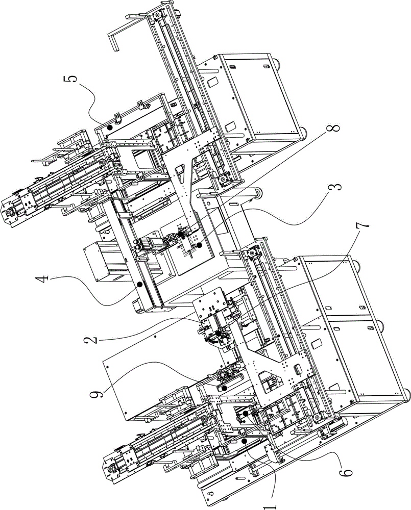
[0030] Such as figure 1 As shown, a fully automatic glass panel printing machine is provided with a feeding device 1 and a rough positioning device 2 at the feeding end, a feeding device 5 at the feeding end, and a fine positioning device between the feeding end and the discharging end. The positioning device 3 is provided with a printing device 4 above the fine positioning device 3; a first manipulator 6 is arranged between the described feeding device 1 and the rough positioning device 2, and between the described rough positioning device 2 and the fine positioning device 3 A second manipulator 7 is provided, and a third manipulator 8 is arranged between the fine positioning device 3 and the unloading device 5; the first manipulator 6 transports the glass panel of the feeding tray in the feeding device 1 to the rough positioning device 2 rough positioning,...


PUM


Abstract

The invention discloses a full-automatic glass panel printing machine. A feeding device and a rough positioning device are arranged at a feeding end, a discharging device is arranged at a discharging end, and a fine positioning device is arranged between the feeding end and the discharging end. A printing device is arranged above the fine positioning device. A first mechanical arm is arranged between the feeding device and the rough positioning device, a second mechanical arm is arranged between the rough positioning device and the fine positioning device, and a third mechanical arm is arranged between the fine positioning device and the discharging device. A glass panel of a material plate in the feeding device is conveyed into the rough positioning device to receive rough positioning through the first mechanical arm, the glass panel on which rough positioning is conducted is conveyed into the fine positioning device to receive fine positioning through the second mechanical arm, and the printed glass panel is conveyed onto a material plate in the discharging device through the third mechanical arm. The feeding device and the discharging device are each provided with an automatic panel changing structure and an automatic panel stacking structure.

Description

technical field [0001] The invention relates to the technical field of glass screen printing equipment, in particular to a fully automatic glass panel printing machine. Background technique [0002] Modern production is already an era of automated production, but many manufacturers have to use a lot of manual work due to limited input costs. In the current glass production field, glass printing equipment is an important process of glass processing. Many manufacturers still use manual as the carrier of material delivery. Although the existing glass printing equipment has a high degree of automation, it still lacks supporting automation. The loading and unloading equipment, so that the automatic production efficiency of glass printing equipment still needs to be improved. Moreover, manual mixing into automated production can easily cause some dangerous situations and damage the interests of personnel and manufacturers. [0003] Moreover, the current feeding device can only r...

Claims


Application Information

Patent Timeline
Patent Type & Authority Applications(China)
IPC IPC(8): B41F15/14
Inventor 胡炜薛超帅红文李建荣刘正勇丁彪
Owner DONGGUAN RBD TECH
Why Eureka
Try Eureka