
Needle type sucker

A suction cup and pin-type technology, applied in the direction of conveyor objects, transportation and packaging, etc., can solve the problems of high physical consumption, increased labor costs, and large manpower investment, and achieve low manufacturing costs, reasonable structural design, and high automation. Effect

Inactive Publication Date: 2015-10-07
EFORT INTELLIGENT EQUIP CO LTD
View PDF6 Cites 7 Cited by
  • Summary
  • Abstract
  • Description
  • Claims
  • Application Information

AI Technical Summary

Problems solved by technology

Industrial products not only pay attention to safety and practicality, but also have high requirements on appearance quality; their structural components are complex and changeable, ranging from large to small, heavy to light, and some products can be transported by vacuum adsorption; but for air permeability and Non-steel products cannot be transported by vacuum adsorption. In mass production, manual transport is generally used, which takes time and effort, consumes a lot of physical strength, and requires more manpower. In addition, there are generally more dust and chemical additives in this industry. The environment of the workshop is poor, which can cause great harm to the body of the workers. The labor intensity of the workers is high, the efficiency is low, the labor cost increases year by year, and labor shortages occur. Therefore, this industry urgently needs to adopt automated production workshops to reduce labor costs. investment, so in order to realize automatic production, it is particularly important in this industry for manipulators to automatically grab workpieces

Method used


Image

  • Needle type sucker

Examples


Embodiment Construction

[0011] In order to make the purpose, technical solutions and beneficial effects of the present invention more clear, the preferred embodiments of the present invention will be described in detail below in conjunction with the accompanying drawings, and the present invention will be further described to facilitate the understanding of technical personnel.

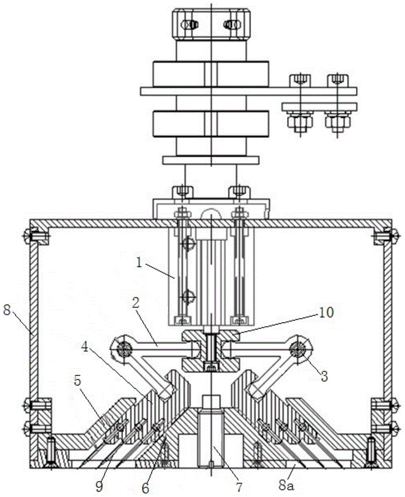
[0012] Such as figure 1 As shown, a needle sucker includes a cylinder 1, a lever 2, a shaft 3, a slider 4, an upper fixed slider 5, a lower fixed slider 6, an adjustment rod 7, a frame 8, a steel needle 9 and an adapter block 10. The upper end of the cylinder 1 is fixed on the frame 8 by screws, the adapter block 10 is fixed on the piston rod of the cylinder 1, the driving rod 2 has a V-shaped structure, and the number of the driving rods 2 is two root, two driving rods 2 are symmetrically distributed on the left and right sides below the adapter block 10, the shaft 3 passes through the corners of the driving rod 2 correspon...


PUM


Abstract

The invention discloses a needle type sucker. The needle type sucker comprises an air cylinder, stirring rods, shafts, sliding blocks, an upper fixing sliding block, a lower fixing sliding block, an adjusting rod, a frame, steel needles and a joint block. The upper end of the air cylinder is fixed to the frame. The joint block is fixed to a piston rod of the air cylinder. The two stirring rods are symmetrically distributed on the left side and the right side below the joint block. The shafts correspondingly penetrate through the corners of the stirring rods. The front ends and the rear ends of the shafts are fixedly connected with the frame. The upper ends of the stirring rods are hinged to the joint block. The number of the sliding blocks is two. The lower ends of the stirring rods are correspondingly hinged to the two sliding blocks respectively. The two sliding blocks are in sliding fit with the left side and the right side of the lower fixing sliding block respectively. The two sliding blocks are attached to the end face of the upper fixing sliding block. The steel needles are installed at the lower portions of the two sliding blocks respectively. The needle type sucker has the advantages that the structural design is reasonable, the automation degree is high, and the manufacturing cost is low. Permeability and non-rigidity workpiece carrying are achieved through a needling mode, the carrying efficiency is improved, and stability is high.

Description

technical field [0001] The invention relates to the technical field of air permeability and non-steel workpiece handling, in particular to a needle sucker. Background technique [0002] The rapid development of automated industrial machinery, the substantial increase in production capacity and strict cost control put forward higher requirements for automated production lines. Industrial products not only pay attention to safety and practicality, but also have high requirements on appearance quality; their structural components are complex and changeable, ranging from large to small, heavy to light, and some products can be transported by vacuum adsorption; but for air permeability and Non-steel products cannot be transported by vacuum adsorption. In mass production, manual transport is generally used, which takes time and effort, consumes a lot of physical strength, and requires more manpower. In addition, there are generally more dust and chemical additives in this industry...

Claims


Application Information

Patent Timeline
IPC IPC(8): B65G47/74
Inventor 王小秋董茂年谢春林李启余李兴海周涛
Owner EFORT INTELLIGENT EQUIP CO LTD
Learn More