Energy-saving type airlock discharger

A technology for shutting off fans and unloaders, which is applied in the field of shutting down fans, and can solve problems such as reduced use costs, high use costs, and poor wind-off effects, and achieves the effects of reduced use costs, convenient manufacturing, and reduced air leakage

Inactive Publication Date: 2015-10-07
付海岗
View PDF7 Cites 2 Cited by
  • Summary
  • Abstract
  • Description
  • Claims
  • Application Information

AI Technical Summary

Problems solved by technology

[0006] The purpose of the present invention is to overcome the disadvantages of the prior art, such as the poor effect of shutting off the fan, large output power, heavy body, and high cost of use, and provides an energy-saving type unloader for shutting down the fan, adopting the technology of the present invention The scheme provides power through a micro-motor or a cylinder, so that the two movable plates can be opened or closed to realize material transportation, and the cost of use is greatly reduced. Compared with the fan in the prior art that uses the impeller to close the air, the air is closed tightly. The effect of shutting off the wind is good, and it is not easy to be blocked; the structure is simplified, the weight is reduced, the body is light and handy, and it is convenient to manufacture

Method used


Image

  • Energy-saving type airlock discharger
  • Energy-saving type airlock discharger
  • Energy-saving type airlock discharger

Examples


Embodiment 1

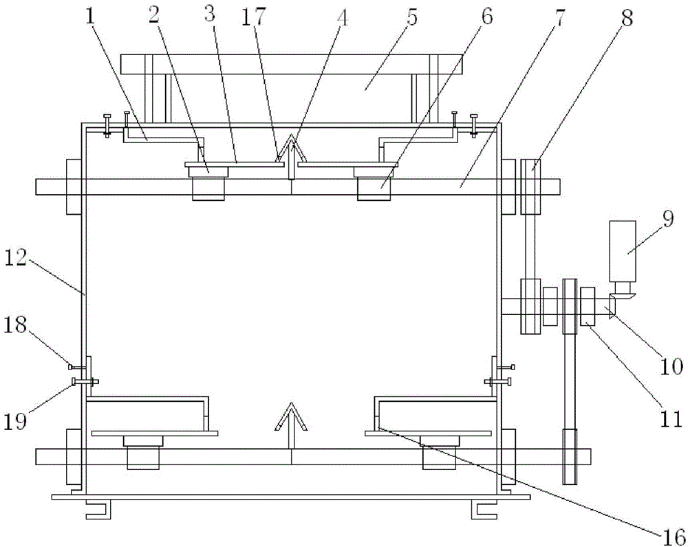
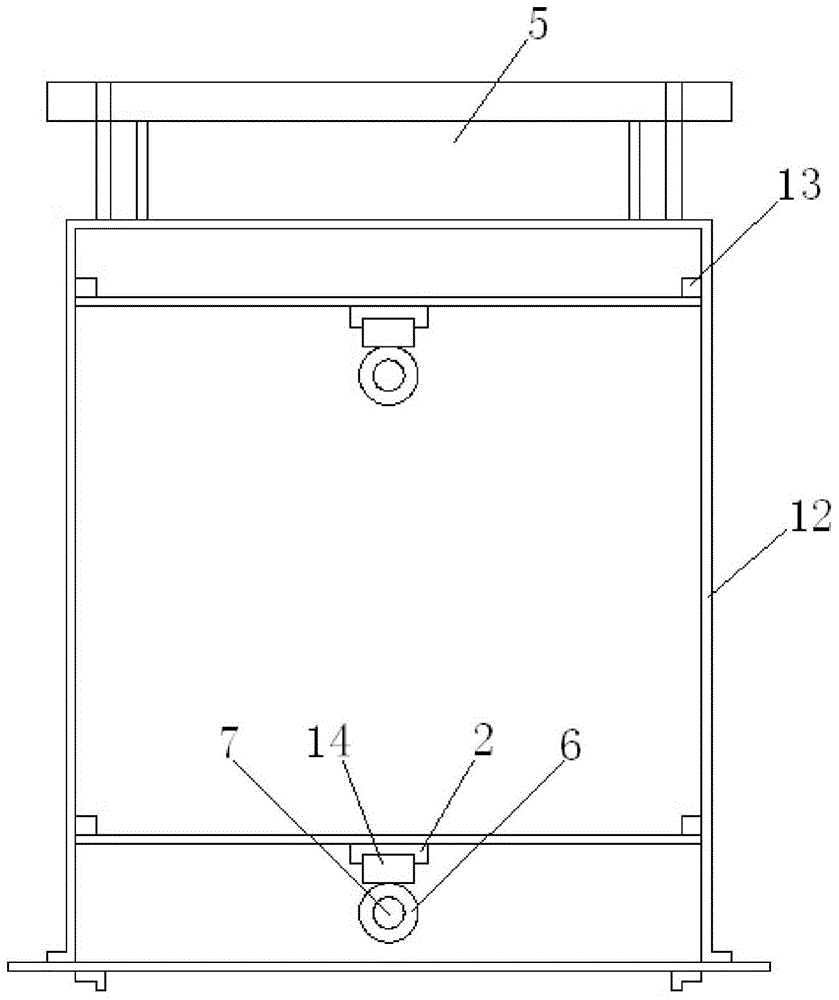
[0032] Such as figure 1 and figure 2 As shown, a kind of energy-saving fan-off unloader of the present embodiment includes a body 12 and a driving mechanism, the upper end of the body 12 is provided with a feed port 5, the lower end is provided with a discharge port, and the inside of the body 12 is provided with a The feeding mechanism of 55 and the blanking mechanism near the discharge port, the feeding mechanism and the blanking mechanism respectively include two movable plates 3, the two movable plates 3 of the feeding mechanism and the two movable plates 3 of the blanking mechanism are both Driven by the driving mechanism to move to both sides to open or move to the middle to close, the two movable plates 3 of the feeding mechanism and the two movable plates 3 of the unloading mechanism open and close alternately to realize the conveying of materials.

[0033] The driving mechanism of the present embodiment is controlled by a control system, and mainly includes a ball s...

Embodiment 2

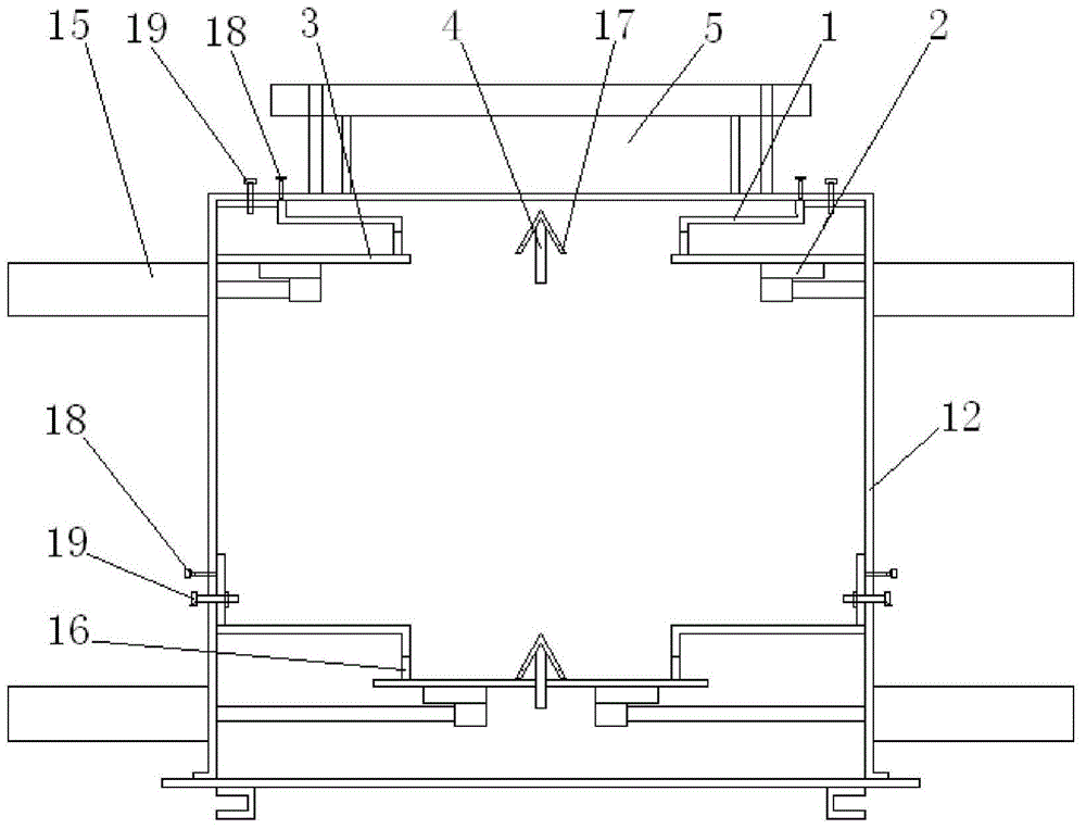
[0038] Such as image 3 and Figure 4 As shown, a kind of energy-saving fan shut-off unloader of this embodiment is basically the same structure as the above-mentioned embodiment 1, the difference is that: the driving mechanism of this embodiment includes a cylinder 15, and the cylinder 15 is installed on the body 12, Corresponding to the movable plate 3, the piston rod of the cylinder 15 extends horizontally to push and pull the movable plate 3 to make a linear movement along the axis of the piston rod, and the movable plate 3 and the piston rod of the cylinder 15 are also passed through the slider. The slide rail mechanism is connected.

[0039] When conveying materials, the control system controls the drive mechanism to drive the two movable plates 3 of the unloading mechanism to move to the middle to close the discharge port, and then drives the two movable plates 3 of the feeding mechanism to move to both sides to open the feed port 5, so that The material passes betwee...


PUM


Abstract

The invention discloses an energy-saving type airlock discharger, and belongs to the field of conveying machines. The energy-saving type airlock discharger comprises a discharger body and driving mechanisms. A feeding opening is formed in the upper end of the discharger body. A discharging opening is formed in the lower end of the discharger body. A feeding mechanism close to the feeding opening and a discharging mechanism close to the discharging opening are arranged inside the discharger body. The feeding mechanism and the discharging mechanism each comprise two movable plates. The two movable plates of the feeding mechanism and the two movable plates of the discharging mechanism are driven by the driving mechanisms to move towards the two sides to be separated or move towards the middle to be combined and are alternately separated and combined to convey materials. By means of the energy-saving type airlock discharger, the output power is small, the use cost can be greatly reduced, and the energy-saving type airlock discharger is economical and practical; compared with an airlock in which air locking is achieved through an impeller in the prior art, air is tightly locked, and the air locking effect is good.

Description

technical field [0001] The invention relates to a shut-off fan, in particular to an energy-saving fan shut-off unloader. Background technique [0002] In the fields of food, pharmaceuticals, environmental protection, metallurgy, chemical industry, etc., during the process of conveying materials, conveying equipment is usually used to convey materials. When conveying materials, the materials are directly conveyed to the next container. During the unloading process, the materials Due to surrounding factors such as wind, the materials will be lifted up and dispersed in the air, polluting the air. Later, in order for the conveying equipment to discharge and unload normally, a discharge device will be connected to the discharge port of the conveying equipment, but this not only increases the cost, but also the discharge device occupies a large area, although it ensures the conveying equipment. Normal nesting, but the investment cost is higher. [0003] In order to solve the abo...

Claims


Application Information

Patent Timeline
Patent Type & Authority Applications(China)
IPC IPC(8): B65G53/46
Inventor 付海岗
Owner 付海岗
Why Eureka
Try Eureka