Road surface sweeper

A cleaning vehicle and cleaning mechanism technology, applied in the field of cleaning vehicles, can solve the problems of low cleaning efficiency on the road surface, small garbage and dust cannot be effectively cleaned, etc., and achieve the effect of simple structure and low cost

Active Publication Date: 2015-10-07
叶建新
View PDF8 Cites 11 Cited by
  • Summary
  • Abstract
  • Description
  • Claims
  • Application Information

AI Technical Summary

Problems solved by technology

[0004] The technical solution provided by the above-mentioned patent documents relies on the sandwich plate and the moving bristles to bring the road garbage into the garbage bin on the top of the car body. Obviously, it cannot effectively clean the smaller garbage and dust.
Moreover, the tug wheel drives the rotating belt and the bristles to move, and the road cleaning efficiency is low

Method used


Image

  • Road surface sweeper
  • Road surface sweeper
  • Road surface sweeper

Examples


Embodiment 1

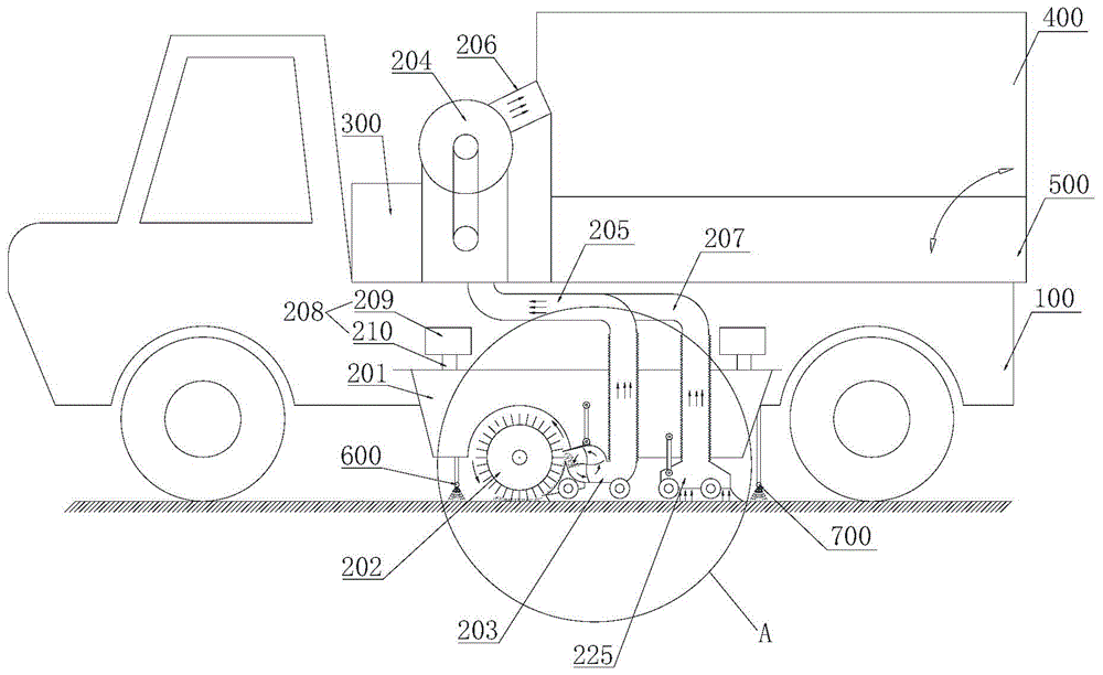
[0063] Example 1, see figure 1 and figure 2 .

[0064] This embodiment provides a road sweeping vehicle, including: a vehicle body 100 , a garbage cleaning mechanism 200 , an electrical control system and a hydraulic control system 300 , a garbage can 400 and a water tank 500 .

[0065] The garbage box 400 and the water tank 500 are disposed on the top of the vehicle body 100 , and the garbage box 400 is located above the water tank 500 . The water tank 500 is fixedly connected or detachably connected with the vehicle body 100, the rear part of the garbage tank 400 is rotationally connected with the water tank 500, and the front part of the garbage tank 400 is connected with the vehicle body 100 through a hydraulic strut. The front part is propped up so that the dustbin 400 can be turned backwards at a certain angle, which is convenient for automatic unloading.

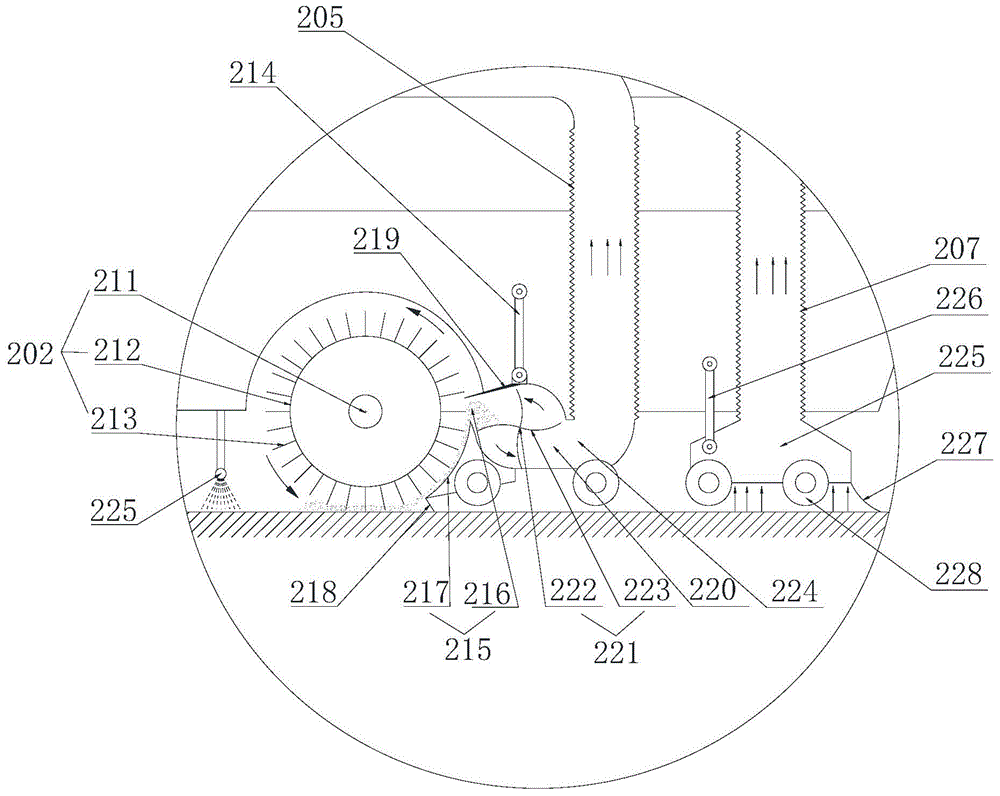
[0066] The garbage cleaning mechanism 200 includes a mounting frame 201 , a cleaning roller 202 , a first sucti...

Embodiment 2

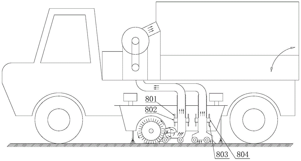
[0079] Example 2, see image 3 .

[0080] This embodiment provides a road garbage cleaning vehicle, and the improvement compared with Embodiment 1 is that the swing bar is replaced by a chute and a slide block. Wherein, the first chute 801 is fixed with the installation frame 201, and the first chute 801 is arranged vertically, the first slider 802 is fixed with the first suction hood 203, and the first slider 802 is slidably embedded in the first slider. In the groove 801; the second chute 803 is fixed with the mounting frame 201, and the second chute 803 is vertically arranged, the second slider 804 is fixed with the second suction hood 225, and the second slider 804 is slidably embedded in the second Inside the second chute 803. When the anti-collision wheel 228 collides with the protrusion, the first air suction cover 203 and the second air suction cover 225 slide upward.


PUM


Abstract

The invention provides a road surface sweeper, and relates to the technical field of sweepers. The road surface sweeper comprises a sweeper body and a garbage can. A garbage sweeping mechanism is installed on the sweeper body and comprises an installing frame, a sweeping roller, a first air suction cover, an induced draft fan, a first air pipe, a second air pipe and a driving mechanism used for driving the sweeping roller and the induced draft fan to rotate. The sweeping roller is arranged at the bottom of the sweeper body and connected with the installing frame in a rotating mode, the rotating axis of the sweeping roller is transversely arranged, and brush bristles are arranged on the circumferential surface of the sweeping roller. The first air suction cover is arranged on the rear side of the sweeping roller and provided with a guiding plate used for being matched with the brush bristles of the sweeping roller to clamp material, a garbage inlet is formed in the upper portion of the guiding plate, and a guiding inclined surface is arranged on the lower portion of the guiding plate and used for guiding garbage into the garbage inlet. An inlet and an outlet of the induced draft fan are communicated with the first air suction cover and the garbage can through the first air pipe and the second air pipe respectively. The road surface sweeper is high in sweeping efficiency and thorough in sweeping.

Description

technical field [0001] The invention relates to the technical field of cleaning vehicles, in particular to a road cleaning vehicle. Background technique [0002] The sweeper is a kind of automatic cleaning equipment, and the sweeper automatically cleans the road surface during its travel. [0003] The application number is that the Chinese patent document of 200520125038.8 discloses a kind of motorized road sweeper, and it comprises a motor vehicle, is connected with cleaning device at the motor vehicle tail, and concrete structure is: connect a bracket at the motor vehicle tail, install on the bracket, There are two lower drums, and the rotating belts with bristles are butt wound on the two drums. One end of one of the drums is fitted with a power transmission wheel. One side of the rotating belt is fixed with a clamping plate, and the clamping plate is close to the rotating drum enough to crook the bristles. The bottom end of the sandwich board is connected with a tooth...

Claims


Application Information

Patent Timeline
Patent Type & Authority Applications(China)
IPC IPC(8): E01H1/08
Inventor 叶建新
Owner 叶建新
Why Eureka
Try Eureka