
Die frame

A frame and mold technology, applied in the field preparation and construction of formwork/template components, building components, etc., can solve the problems of low precision, inaccurate verticality, insufficient pressure resistance, etc., to improve the compressive strength and Bearing capacity, high vertical accuracy, error avoidance effect

Inactive Publication Date: 2015-10-07
王春雷
View PDF6 Cites 3 Cited by
  • Summary
  • Abstract
  • Description
  • Claims
  • Application Information

AI Technical Summary

Problems solved by technology

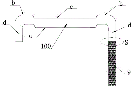
[0002] At present, in the field of construction, the frame structure of the mold used in the production of formwork is as follows: figure 1 As shown, it consists of a bottom edge a, a top edge b, an elastic edge c, and two folds d. When the plane steel block 9 is combined with the frame 100, it is a fold that directly welds the end of the plane steel block 9 to the frame 100. On d, due to the presence of weld seams during welding, the welded place (inside the dotted circle S in the figure) is prone to fracture under greater pressure, the pressure resistance is not enough, and there are weld seams, and leakage is prone to occur during subsequent grouting slurry phenomenon, resulting in poor molding effect and low precision of the filling wall; and this combination formed by welding is not convenient for the repeated use of the frame 100 and the plane steel block 9, and the cost is high; in addition, it is easy to cause verticality due to human factors during welding. Inaccurate, the verticality of the final formed filling wall is not accurate enough; the structure of the current frame is more complicated, and the molding cost is higher

Method used


Image

  • Die frame
  • Die frame
  • Die frame

Examples


Embodiment Construction

[0013] The present invention will be described in detail below in conjunction with the drawings.

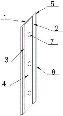
[0014] This embodiment provides a mold frame, such as figure 2 with 3 As shown, the frame is composed of a bottom edge 1, a large flat side 2, a small flat side 3, an elastic side 4, two compression angles 6 and a notch 5 formed by an integrated hot rolling forming process, a large flat side 2 and Between the small flat side 3 is the elastic side 4, the large flat side 2, the small flat side 3 and the elastic side 4 are all parallel to the bottom side 1. An arc-shaped compression resistance is provided at the junction of the large flat side 2 and the elastic side 4 Angle 6, at the junction of the small flat side 3 and the elastic side 4 is also provided with the same pressure-resistant angle 6, between the elastic side 4 and the bottom side 1, there is a row of pin holes 7, at the end of the frame, the large flat side A splicing right-angle notch 5 is opened between 2 and bottom si...


PUM


Abstract

The invention relates to the field of construction dies and discloses a die frame. A flexible edge (4) is located between a large smooth edge (2) and a small smooth edge (3), the distance between the large smooth edge (2) and a bottom edge is equal to the distance between the small smooth edge (3) and the bottom edge and is larger than the distance between the flexible edge (4) and the bottom edge, and a row of bolt holes (7) are further formed between the flexible edge (4) and the bottom edge (1). One crush resistance corner (6) is located at the joint of the large smooth edge (2) and the flexible edge (4), and the other crush resistance corner (6) is located at the joint of the small smooth edge (3) and the flexible edge (4). A notch (5) is located among the end of the frame, the large smooth edge (2) and the bottom edge (1), one side of the notch (5) is parallel to the bottom edge (1), and the other side of the notch (5) is perpendicular to the bottom edge (1). The die frame is simple in structure, the crush resistance bearing capability is high, the perpendicular precision is high, and slurry leakage is effectively avoided.

Description

technical field [0001] The invention relates to the field of building molds, in particular to a mold frame. Background technique [0002] At present, in the field of construction, the frame structure of the mold used in the production of formwork is as follows: figure 1 As shown, it consists of a bottom edge a, a top edge b, an elastic edge c, and two folds d. When the plane steel block 9 is combined with the frame 100, it is a fold that directly welds the end of the plane steel block 9 to the frame 100. On d, due to the presence of weld seams during welding, the welded place (inside the dotted circle S in the figure) is prone to fracture under greater pressure, the pressure resistance is not enough, and there are weld seams, and leakage is prone to occur during subsequent grouting slurry phenomenon, resulting in poor molding effect and low precision of the filling wall; and this combination formed by welding is not convenient for the repeated use of the frame 100 and the p...

Claims


Application Information

Patent Timeline
Patent Type & Authority Applications(China)
IPC IPC(8): E04G9/02
Inventor 张立军张斌郑昕黄国庆
Owner 王春雷
Learn More