Flow distributing type hydraulic oscillation circumferential impactor

A shunt type and impactor technology, which is applied in the direction of vibration drilling, drilling equipment, liquid/gas jet drilling, etc., can solve the problems of poor impact effect and short life, and achieve improved rock breaking efficiency, low cost, and good structure simple effect

Active Publication Date: 2015-10-07
NORTHEAST GASOLINEEUM UNIV
View PDF5 Cites 26 Cited by
  • Summary
  • Abstract
  • Description
  • Claims
  • Application Information

AI Technical Summary

Problems solved by technology

[0004] The object of the present invention is to provide a split-flow hydraulic oscillation circumferential impactor, which i...

Method used


Image

  • Flow distributing type hydraulic oscillation circumferential impactor
  • Flow distributing type hydraulic oscillation circumferential impactor
  • Flow distributing type hydraulic oscillation circumferential impactor

Examples


Embodiment Construction

[0023] The present invention is described further below:

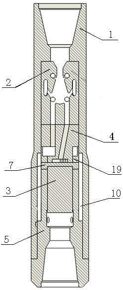
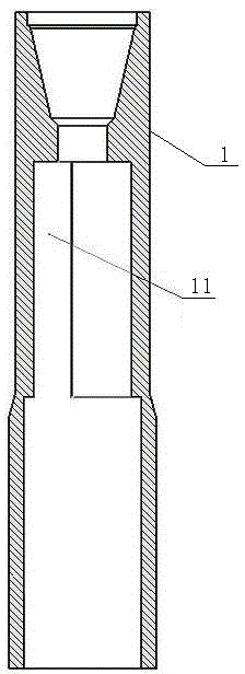
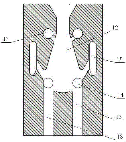
[0024] This shunt type hydraulic oscillation circumferential impactor includes a shell joint 1, a double female jet generator 2, a flow divider 4, a gland 7, a hydraulic hammer 3, and a transmission short 5; the lower end of the shell joint 1 is screwed into the transmission short 5 , the double-female jet generator 2 is placed in the shell joint 1, the hydraulic hammer 3 is located on the upper part of the transmission short-circuit 5, the flow divider 4 and the gland 7 are located between the double-female jet generator 2 and the hydraulic hammer 3, and the transmission short-circuit 5 is screwed into the lower end of the shell joint 1 and pressed against the gland 7; the inner wall of the shell joint 1 has an annular groove 11 and a discharge channel 10, and the annular groove 11 is connected to the liquid return outlet 15 on the outer wall of the double female jet generator 2 Correspondingly set, the discharge chan...


PUM


Abstract

The invention relates to a flow distributing type hydraulic oscillation circumferential impactor. The flow distributing type hydraulic oscillation circumferential impactor comprises a shell connector, a double-bus jet generator, a flow distributor, a gland, a hydraulic drive hammer and a transmission short joint. The double-bus jet generator abuts against the interior of the shell connector. The hydraulic drive hammer is installed at the upper portion of the transmission short joint. The flow distributor and the gland are located between the double-bus jet generator and the hydraulic drive hammer. The transmission short joint is screwed in the lower end of the shell connector and abuts against the gland. An annular groove and a flow releasing channel are formed in the inner wall of the shell connector. The annular groove corresponds to a returned liquid outlet in the outer wall of the double-bus jet generator, and a drainage hole is formed in the transmission short joint. The double-bus jet generator is a cylinder with a center runner. The center runner is divided into a left branch runner and a right branch runner through a check block. The inlet and the outlet of a pressure feedback channel in the double-bus jet generator are communicated with the center runner. Each branch runner is divided into two parts through the flow distributor. The hydraulic drive hammer is provided with symmetric arc bosses. Arc cavities contain the arc bosses. According to the flow distributing type hydraulic oscillation circumferential impactor, no weak part exists, the service life is long, and the impact effect is good.

Description

technical field [0001] The invention relates to a drilling tool used in medium-hard to hard formations in the petroleum industry, in particular to a split-flow hydraulic oscillation circumferential impactor. Background technique [0002] Driven by the two factors of increasing scarcity of oil resources and sharp increase in demand, the exploration and development of the new area continues to expand, the depth of oil production wells continues to deepen, the formations encountered are becoming more and more complex, the loss of power along the way is large, and the liquid column is on the well. The holding effect of the bottom is obvious, the drilling speed is slow, and the tools are easily damaged, which leads to a longer drilling cycle and higher drilling costs, which seriously restrict the development process of oil and gas fields. Therefore, increasing the penetration rate of deep wells and ultra-deep wells is an urgent need for oilfields at home and abroad. [0003] At ...

Claims


Application Information

Patent Timeline
IPC IPC(8): E21B4/16E21B7/18E21B7/24
Inventor 李玮纪照生李士斌孙晓峰任永良赵增伟
Owner NORTHEAST GASOLINEEUM UNIV
Why Eureka
Try Eureka