
Torsion rubber core

A rubber core and torsion technology, which is applied to springs, springs/shock absorbers, and mechanical equipment made of plastic materials, can solve problems such as difficult buffering, fracture of the upper and lower covers of the ball pins, and affecting the service life of the torsion rubber core. Achieve the effect of stable improvement, low cost and simple structure

Active Publication Date: 2015-10-07
福建省博勇机械制造有限公司
View PDF15 Cites 5 Cited by
  • Summary
  • Abstract
  • Description
  • Claims
  • Application Information

AI Technical Summary

Problems solved by technology

Although the structure of this torsion rubber core is relatively simple, but the torsion rubber core is subjected to a large bearing capacity, and the shock absorber will be separated from the ball pin, making it difficult to play the proper buffering effect.
At the same time, in this scheme, the upper cover and the lower cover are further used to avoid the slippage of the shock absorber. However, at this time, the connection between the upper and lower cover and the ball pin is a stress concentration point, which is easy to cause the ball pin or the upper and lower covers. Fracture, which affects the service life of the torsion rubber core

Method used


Image

  • Torsion rubber core
  • Torsion rubber core
  • Torsion rubber core

Examples


Embodiment Construction

[0040] In order to further explain the technical solution of the present invention, it will be described in detail below in conjunction with the accompanying drawings.

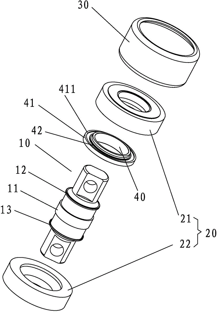
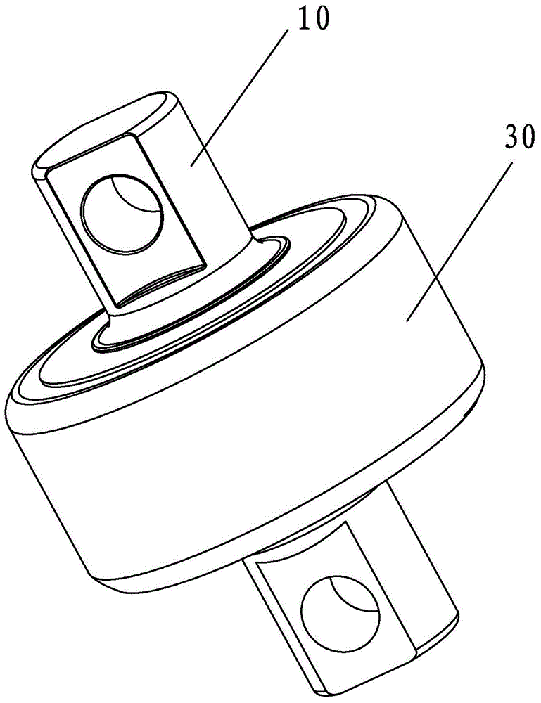
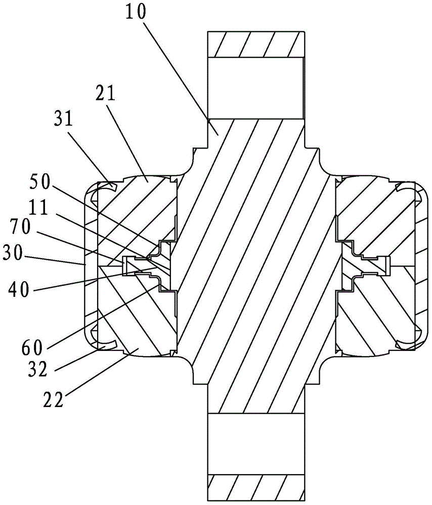
[0041] refer to Figure 1 to Figure 5 , a torsion rubber core, comprising a torsion rubber mandrel 10, a rubber pad 20 sleeved on the torsion rubber mandrel 10 and a fastening sleeve 30 sleeved outside the rubber pad 20, the rubber pad 20 is a rubber pad, tight The fixed sleeve 30 adopts a steel sleeve, and the surface of the fastening sleeve 30 is provided with an electroless chrome plating layer to enhance the corrosion resistance and wear resistance of the fastening sleeve 30 .

[0042] The present invention also includes an elastic piece 40 sleeved on the torsion rubber mandrel 10, a support portion 41 is formed on the elastic piece 40, the elastic piece 40 is processed into a corresponding shape by a seamless tube, and the rubber pad 20 includes a The first rubber pad 21 and the second rubber pad 22 on b...


PUM


Abstract

The invention relates to a torsion rubber core. The torsion rubber core comprises a torsion rubber core shaft, a rubber cushion, an adapter sleeve and an elastic sheet arranged on the torsion rubber core shaft in a sleeved mode; a supporting part is formed in the elastic sheet, the rubber cushion comprises a first rubber cushion and a second rubber cushion arranged on two sides of the supporting part respectively, two end faces of the first rubber cushion are provided with a first pressing face and a first supporting face in the axial direction respectively, two end faces of the second rubber cushion are provided with a second pressing face and a second supporting face in the axial direction respectively, the first supporting face and the second supporting face are pressed on the supporting part in an abut against mode correspondingly, and the torsion rubber core shaft is tightly sleeved with the first rubber cushion and the second rubber cushion. Therefore, by arranging the elastic sheet on the torsion rubber core shaft, the elastic sheet is matched with the first rubber cushion and the second rubber cushion, better damping and buffering functions are played, meanwhile movements of the first rubber cushion and the second rubber cushion can be further limited by the elastic sheet to a certain degree, the stability of the whole rubber cushion is guaranteed, the torsion resistance of the whole torsion rubber core is improved, and meanwhile according to the torsion rubber core, the structure is relatively simple, and the cost is low.

Description

technical field [0001] The invention belongs to the field of auto parts, and in particular relates to a torsion rubber core. Background technique [0002] The torsion rubber core of the thrust rod assembly is mainly used for guiding and force transmission, and the push-pull force and torsion force received are very large. At present, the connecting shaft is generally a spherical shaft or a shaft with support plates on both sides. The connecting shaft is wrapped on its surface. Elastomers such as rubber or polyurethane are used to cushion the impact of push-pull and torsional movements. During use, an overload impact is likely to occur between the connecting shaft and the elastic body, causing the elastic body to expand, deform, overflow, and wear aggravated, eventually resulting in damage to the elastic body, deformation and fracture of the connecting shaft, and the scrapping of the thrust rod assembly. [0003] For this reason, in the Chinese utility model patent entitled ...

Claims


Application Information

Patent Timeline
IPC IPC(8): F16F1/38
CPCF16F1/38
Inventor 蔡耀强
Owner 福建省博勇机械制造有限公司
Learn More