Small-tooth-difference high-precision cycloid gear speed reducer

A cycloid gear and reducer technology, applied in the direction of gear transmission, belt/chain/gear, mechanical equipment, etc., can solve the problem of affecting the deceleration accuracy of the reducer, inability to achieve high transmission ratio, cycloid wheel and needle roller clearance, etc. problems, to achieve the effect of saving installation space, high transmission ratio, and realizing transmission ratio

Inactive Publication Date: 2015-10-07
CHANGZHOU XINWEI ELECTRONICS CO LTD
View PDF5 Cites 3 Cited by
  • Summary
  • Abstract
  • Description
  • Claims
  • Application Information

AI Technical Summary

Problems solved by technology

[0002] The planetary reducer cycloidal pinwheel reducer used in the existing market is relatively large in size and will occupy a large space during use, especially in the cycloidal pinwheel reducer, the pendulum in the reducer The thread wheel and the needle rollers in the outer ring cooperate with each other. There is a large gap between the cycloid wheel and the needle roller, and it is impossible to achieve a tight fit. There will be some rotation gaps. Due to the existence of these rotation gaps, With the long-term rotation of the cycloid reducer, the deceleration accuracy of the reducer will be affected
[0003] Secondly, the traditional planetary reducer cycloid reducer cannot achieve a high transmission ratio

Method used


Image

  • Small-tooth-difference high-precision cycloid gear speed reducer
  • Small-tooth-difference high-precision cycloid gear speed reducer
  • Small-tooth-difference high-precision cycloid gear speed reducer

Examples


Embodiment Construction

[0041] The present invention will be further described in conjunction with specific embodiment now. These drawings are simplified schematic diagrams only to illustrate the basic structure of the present invention in a schematic way, so they only show the components relevant to the present invention.

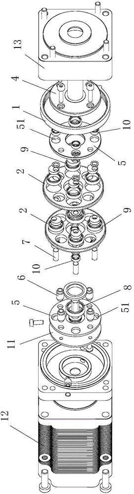
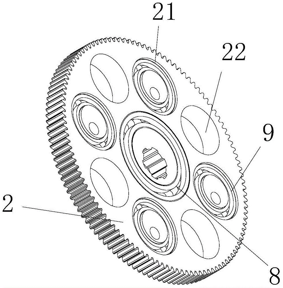
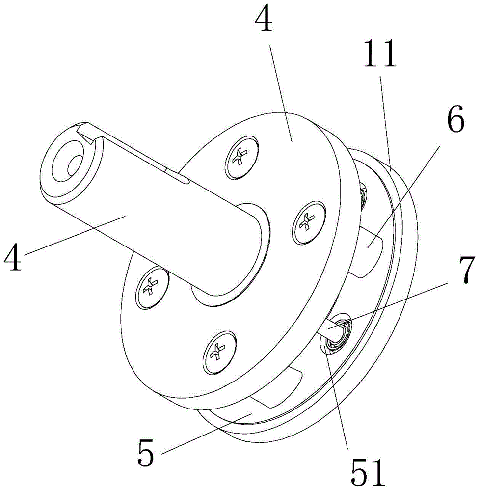
[0042] Such as Figure 1 to Figure 5 As shown, a high-precision cycloidal gear reducer with less tooth difference includes an input shaft 3, a reduction mechanism and an output shaft 4, and the reduction mechanism is respectively connected to the input shaft 3 and the output shaft 4; the reduction mechanism includes a ring gear 1, at least one The cycloid gear 2 located in the ring gear 1, the cage for rotation and at least one eccentric shaft 7 for cooperating with the cycloid gear 2 and driving the cage to rotate, the output shaft 4 is fixedly connected with the cage.

[0043]The cycloid tooth piece 2 is eccentrically arranged on the input shaft 3 through the first eccentric a...


PUM


Abstract

The invention relates to a small-tooth-difference high-precision cycloid gear speed reducer which comprises an input shaft, a speed reduction mechanism and an output shaft. The speed reduction mechanism comprises a tooth ring, cycloid tooth pieces, a holder and eccentric shafts. The cycloid tooth pieces are eccentrically arranged on the input shaft through a first eccentric assembly. The holder comprises two holding end covers and connecting columns. The connecting columns are connected with and located on the holding end covers. The eccentric shafts penetrate through tooth penetrating shaft holes. A second eccentric assembly is arranged between the eccentric shafts and the tooth penetrating shaft holes of the cycloid tooth pieces. The two holding end covers are provided with cover penetrating shaft holes respectively. A third eccentric assembly is arranged between the two ends of the eccentric shafts and the cover penetrating shaft holes of the holding end covers. The cycloid gear speed reducer is small in size, all speed reduction parts can achieve close fitting, the precision of the whole speed reducer is improved, and the high transmission ratio can be achieved.

Description

technical field [0001] The invention relates to a cycloidal gear reducer with small tooth difference and high precision. Background technique [0002] The planetary reducer cycloidal pinwheel reducer used in the existing market is relatively large in size and will occupy a large space during use, especially in the cycloidal pinwheel reducer, the pendulum in the reducer The thread wheel and the needle rollers in the outer ring cooperate with each other. There is a large gap between the cycloid wheel and the needle roller, and it is impossible to achieve a tight fit. There will be some rotation gaps. Due to the existence of these rotation gaps, The long-term rotation of the cycloid reducer will affect the deceleration accuracy of the reducer. [0003] Secondly, the traditional planetary reducer cycloid reducer cannot achieve a high transmission ratio. Contents of the invention [0004] The technical problem to be solved by the present invention is to overcome the deficienc...

Claims


Application Information

Patent Timeline
Patent Type & Authority Applications(China)
IPC IPC(8): F16H1/28
CPCF16H1/28
Inventor 屠志伟丁圣松
Owner CHANGZHOU XINWEI ELECTRONICS CO LTD
Why Eureka
Try Eureka