
Combined air-conditioning system

A combined air-conditioning and air-conditioning system technology, which is applied in the direction of air-conditioning systems, ventilation systems, heating and ventilation control systems, etc., can solve the problems of low heating speed and heating efficiency, frosting, defrosting, and large heat loss, etc., to achieve Improve heat transfer uniformity, reduce heat loss, and improve reliability

Active Publication Date: 2015-10-07
GD MIDEA HEATING & VENTILATING EQUIP CO LTD +1
View PDF9 Cites 15 Cited by
  • Summary
  • Abstract
  • Description
  • Claims
  • Application Information

AI Technical Summary

Problems solved by technology

[0002] In the related art, the computer room air conditioner assembly (the first air conditioner assembly) is mainly used for cooling and cooling the computer room, wherein the compressor releases a large amount of heat due to compressing the refrigerant, while other air conditioner assemblies need to perform heating When working (such as heating mode or defrosting mode, etc.), the heat cannot be recovered and utilized, resulting in a waste of energy. In addition, when the temperature is low in winter, the room air conditioner assembly (second air conditioner assembly) The heat rate and heating efficiency are low, and problems such as frosting and defrosting often occur during the heating process
[0003] In addition, for the heat compensation process between multiple air-conditioning systems, if air-cooled heat exchangers are used for heat exchange between all air-conditioning systems, the heat in the long-distance air-conditioning system During transmission, the use of traditional refrigerants causes excessive heat loss and uneven heat transmission, which can easily cause local temperature of the system to be overcooled or overheated, and even cause the entire air conditioner system to fail in severe cases

Method used


Image

  • Combined air-conditioning system
  • Combined air-conditioning system
  • Combined air-conditioning system

Examples


Embodiment Construction

[0039] In order to understand the above-mentioned purpose, features and advantages of the present invention more clearly, the present invention will be further described in detail below in conjunction with the accompanying drawings and specific embodiments. It should be noted that, in the case of no conflict, the embodiments of the present application and the features in the embodiments can be combined with each other.

[0040] In the following description, many specific details are set forth in order to fully understand the present invention. However, the present invention can also be implemented in other ways different from those described here. Therefore, the protection scope of the present invention is not limited by the specific details disclosed below. EXAMPLE LIMITATIONS.

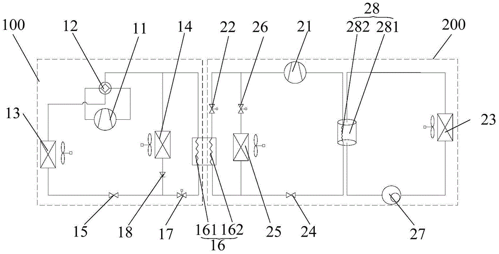
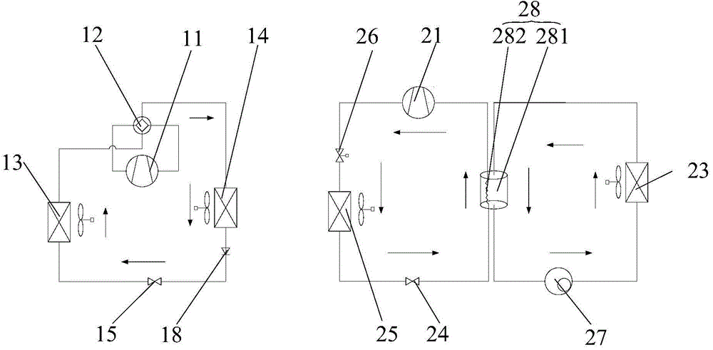
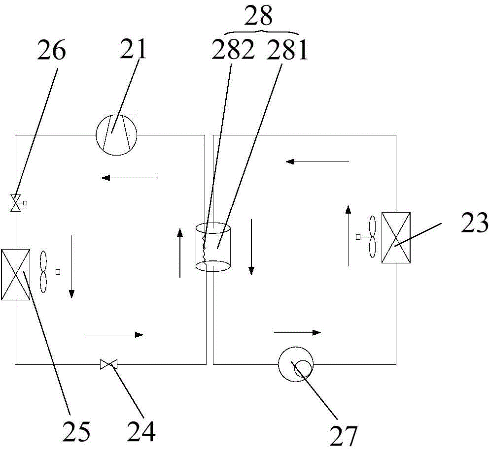
[0041] Refer below Figure 1 to Figure 4 The combined air conditioning system according to some embodiments of the present invention is described.

[0042] Such as figure 1 As shown, the combined ...


PUM


Abstract

The invention provides a combined air-conditioning system, comprising a room air-conditioning system and a machine room air-conditioning system connected with the room air-conditioning system. A heat transferring medium in the room air-conditioning system can perform heat exchange with a heat transferring medium in the machine room air-conditioning system. A control device controls on-off of a bypass-valve, a main valve body, and an auxiliary valve body according to operating mode of the room air-conditioning system, so as to change flowing paths of the heat transferring medium in the air-conditioning system. Thus, on the basis of ensuring stable operation of the machine room air-conditioning system, the room air-conditioning system can fully recycle and use heat exhausted by the machine room air-conditioning system in an operation process, preventing conditions in the prior art that an outdoor heat exchanger frosts and heating efficiency is low caused by using outdoor environment temperature. A liquid pump, an evaporator, and a heat exchange reservoir form a cold-carrying circulation loop, and reliability of long distance heat transport of the machine room air-conditioning system is improved.

Description

technical field [0001] The invention relates to the technical field of air conditioning, in particular to a combined air conditioning system. Background technique [0002] In the related art, the computer room air conditioner assembly (the first air conditioner assembly) is mainly used for cooling and cooling the computer room, wherein the compressor releases a large amount of heat due to compressing the refrigerant, while other air conditioner assemblies need to perform heating When working (such as heating mode or defrosting mode, etc.), the heat cannot be recovered and utilized, resulting in a waste of energy. In addition, when the temperature is low in winter, the room air conditioner assembly (second air conditioner assembly) The heat rate and heating efficiency are low, and problems such as frosting and defrosting often occur during the heating process. [0003] In addition, for the heat compensation process between multiple air-conditioning systems, if air-cooled hea...

Claims


Application Information

Patent Timeline
IPC IPC(8): F24F5/00F24F11/00F25B41/04F24F12/00F25B41/20
CPCF24F5/00F24F11/30F24F11/62F24F12/00F24F11/65F25B41/20
Inventor 王飞陈得宗王密史作君张宝成
Owner GD MIDEA HEATING & VENTILATING EQUIP CO LTD
Learn More