Field-operation optical cable

A field optical cable and optical fiber technology, applied in the field of optical cable, can solve the problems of the optical cable being unable to guarantee the service life, losing the communication function, delaying the acquisition of real-time information, etc., achieving good tensile strain capacity, avoiding compression damage, and maximizing the buffer effect. Effect

Inactive Publication Date: 2015-10-07
CHENGDU HENGTONG ZHAOYE PRECISION MACHINERY
View PDF5 Cites 2 Cited by
  • Summary
  • Abstract
  • Description
  • Claims
  • Application Information

AI Technical Summary

Problems solved by technology

[0003] Due to the lack of metal as a supporting structure in the existing optical cables, under complex field environmental conditions, it is difficult to avoid the optical cables being crushed by heavy objects during use, such as military vehicles, or the oppression of heavy objects such as falling rocks in mountains, which will cause It is seriously damaged and loses its communication function, which hinders the acquisition of real-time information; and the field environment often encounters wind and rain, and ordinary optical cables cannot guarantee its long service life

Method used


Image

  • Field-operation optical cable

Examples


Embodiment 1

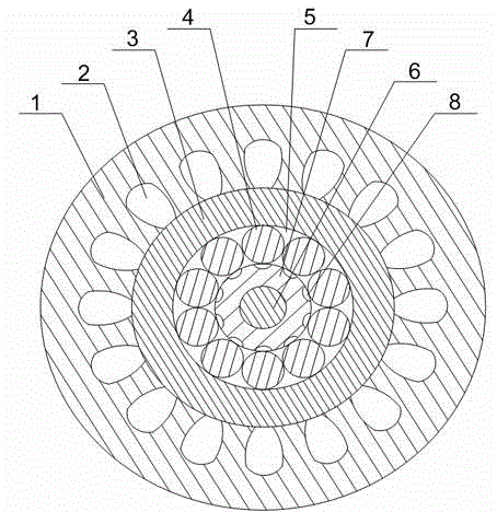
[0020] Such as figure 1 As shown, this embodiment includes a casing 3, and a polyurethane sheath 1 is sheathed on the outer wall of the casing 3, and a plurality of buffer grooves 2 are opened on the inner wall of the polyurethane sheath 1 along its axial direction, so that The two side walls of the buffer groove 2 are bent away from its center, the bottom of the buffer groove 2 expands outward along the radial direction of the polyurethane sheath 1, and a plurality of optical fibers 4 are arranged inside the casing 3, and a plurality of The optical fiber 4 is helically twisted on the aramid fiber tube 7 located in the middle of the sleeve 3, and the fiber paste 5 is filled between the sleeve 3 and the aramid fiber tube 7, and the aramid fiber The outer wall of the tube 7 is also provided with a plurality of spiral grooves 8 with arc-shaped cross-sections corresponding to the optical fibers 4 ; it also includes an FRP reinforcement 6 , and the FRP reinforcement 6 is arranged i...


PUM


Abstract

The invention discloses a field-operation optical cable. The optical cable comprises a casing pipe. A polyurethane sheath sleeves an outer wall of the casing pipe. An inner wall of the polyurethane sheath is provided with a plurality of buffer slots. Two side walls of each buffer slot are bended towards a direction which is far away from a center. A plurality of optical fibers are arranged in the casing pipe. The plurality of optical fibers are twisted on an aramid fiber pipe. An outer wall of the aramid fiber pipe is provided with a plurality of spiral grooves. When the optical cable is rolled and pressed by a vehicle or a drop stone in a field environment, the buffer slots divide a connection portion between the polyurethane sheath and the casing pipe into a plurality of protuberances. When an outer wall of the polyurethane sheath is under stress, the protuberances can be deformed in the two adjacent buffer slots. Through an interaction of an elastic force generated during deformation recovery of the protuberances and pressure, the actual pressure on the casing pipe is greatly reduced so that the optical fiber in the casing pipe is prevented from being pressed and damaged, and the service life of the optical cable in the field environment is prolonged.

Description

technical field [0001] The invention relates to an optical cable, in particular to a field optical cable. Background technique [0002] The military field optical cable is a metal-free optical cable specially designed for use in field operations and complex environments that require rapid routing or repeated retractable use. It is light in weight and easy to carry; it is resistant to tension, pressure, and high in strength-to-weight ratio; softness Good, easy to bend; oil-resistant, wear-resistant, flame-retardant; wide range of applicable temperature, etc., suitable for rapid wiring or repeated retraction of military field communication systems; radar, aviation and ship wiring; oil fields, mines, ports, TV live broadcast , emergency repair of communication lines and other special occasions. [0003] Due to the lack of metal as a supporting structure in the existing optical cables, under complex field environmental conditions, it is difficult to avoid the optical cables bei...

Claims


Application Information

Patent Timeline
Patent Type & Authority Applications(China)
IPC IPC(8): G02B6/44
CPCG02B6/443G02B6/4427G02B6/4432G02B6/4478
Inventor 吴光武
Owner CHENGDU HENGTONG ZHAOYE PRECISION MACHINERY
Why Eureka
Try Eureka