Enameled assembly transposition conducting wire

A technology of transposition conductors and transposition wires, which is applied in the direction of conductors, insulated conductors, insulated cables, etc., and can solve problems such as insulation damage of enamelled copper flat wires, shortening the length of transposition cycles, and movement of enamelled copper flat wires, etc. To achieve the effect of ensuring product quality and safety, shortening the complete transposition cycle, and reducing the possibility

Active Publication Date: 2015-10-07
WUXI XIZHOU MAGNET WIRES
View PDF10 Cites 0 Cited by
  • Summary
  • Abstract
  • Description
  • Claims
  • Application Information

AI Technical Summary

Problems solved by technology

At present, the transposition cores constituting the transposition wires are all formed by a single enamelled flat wire in turn. Once there are too many transposition cores, for example, 60 to 80 transposition cores, the transposition cycle The length will reach 4m ~ 5m, and usually when the length of a complete transposition cycle of the transposed wire is less than 3m, the winding requirements of the transformer coil can be met. When the length of the transposition cycle exceeds 3m, paint will be generated during the coil winding process. The copper-clad flat wire moves, causing the insulation damage of the enamelled copper flat wire, causing a short circuit
Chinese patent CN201210295349.3 discloses that every two enamelled copper flat wires superimposed adjacent to each other make the same rotation cycle transposition along the narrow surface at the same time to shorten the length of the transposition cycle, but eddy currents are found during the winding process of the transformer winding The possibility of loss is high. After a lot of experiments, we found that the reason is that there is a potential difference between the enamelled copper flat wires of the transposed wires.

Method used


Image

  • Enameled assembly transposition conducting wire
  • Enameled assembly transposition conducting wire
  • Enameled assembly transposition conducting wire

Examples


Embodiment Construction

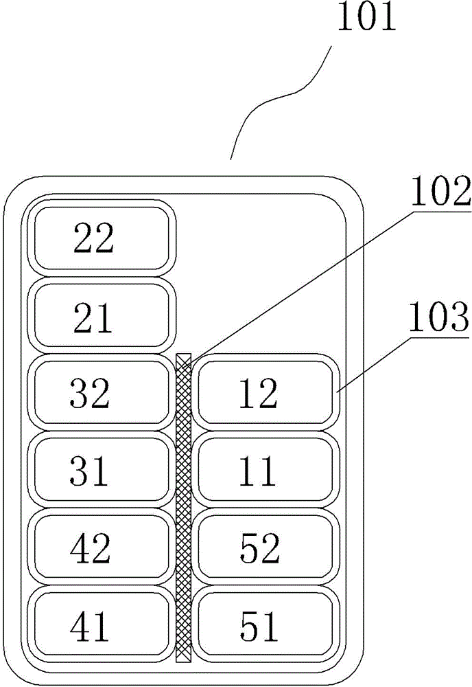
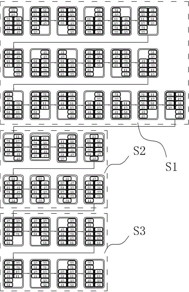
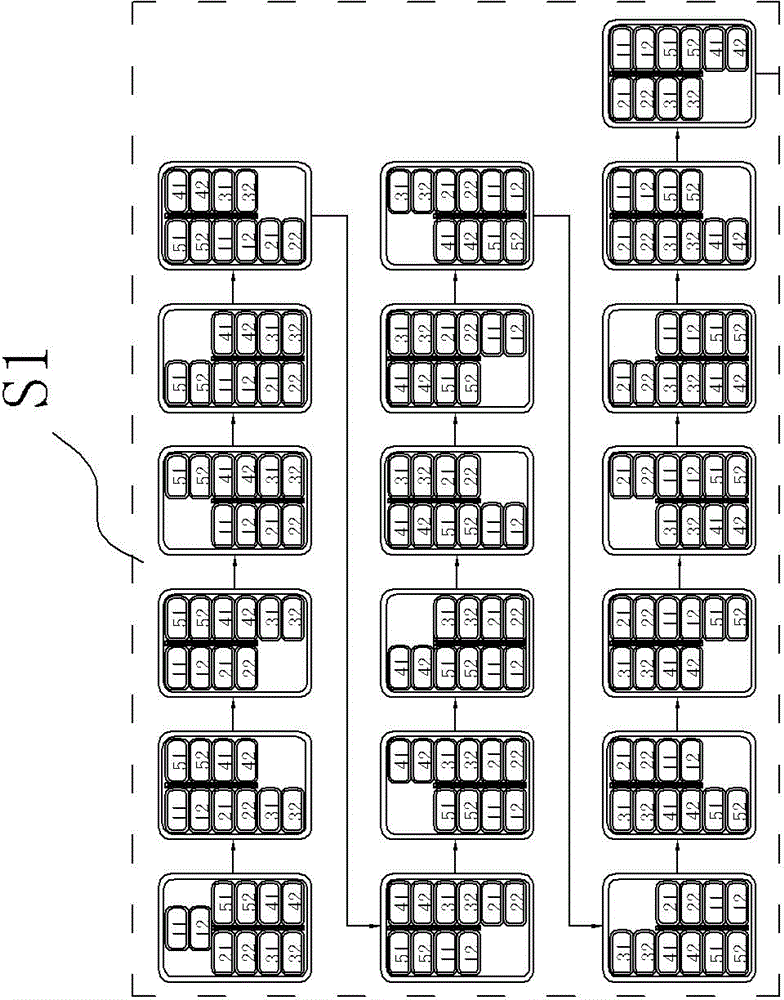
[0014] Such as figure 1 , figure 2 , Figure 2-1 to Figure 2-3 As shown, the enamelled composite transposed wire 101 includes several transposed wire cores, figure 1 Among them, 11, 12, 21, 22, 31, 32, 41, 42, 51, and 52 are all transposition cores, and the transposition cores are composed of an even number of enamelled copper flat wires superimposed on each other according to the wide surface. Two rows, two enamelled copper flat wires adjacent to each other up and down constitute a group, and each group of enamelled copper flat wires performs a circular transposition in the same direction along the narrow surface in sequence, as shown in diagram 2-1 As shown, enamelled copper flat wires 11 and 12 form a group, enameled copper flat wire 11 is superimposed on enamelled copper flat wire 12, enamelled copper flat wires 21 and 22 form a group, enameled copper flat wire 21 is superimposed Above the enamelled copper flat wire 22, the enamelled copper flat wires 31 and 32 form a...


PUM


Abstract

The invention provides an enameled assembly transposition conducting wire, which can realize a small transposition cycle length, avoid displacement, insulated damage and short circuit phenomena of an enameled copper flat wire during a coil winding process, further realize a uniform enameled copper flat wire length after transposition, have no potential difference after a transformer winding is wound, and reduce possibility of generation of eddy current loss. The enameled assembly transposition conducting wire comprises a transposition wire core, the transposition wire core comprises an even number of enameled copper flat wires mutually superimposed and combined into two lines side by side according to wide surfaces, two vertical adjacent enameled copper flat wires of each line form a group, and each enameled copper flat wire group is subjected to cycle transposition in the same turning direction along the narrow surface. The enameled assembly transposition conducting wire is characterized in that after each enameled copper flat wire group performs one circle, one single enameled copper flat wire is subjected to transposition in the same turning direction along the narrow surface so as to enable two enameled copper flat wires forming each enameled copper flat wire group to realize upper and lower transposition.

Description

technical field [0001] The invention relates to the technical field of production of transposed wires, in particular to the field of transposed wires for power transformers, in particular to enamelled combined transposed wires. Background technique [0002] Transposition wire refers to the combination of a certain number of enameled copper flat wires into two rows in which the wide surfaces are in contact with each other, and the transposition of the same direction is made on the top and bottom of the two rows of enameled wires along the narrow surface as required, and is covered with electrical insulating paper. The belt is composed of multiple layers of continuous and tightly wrapped. At present, the transposition cores constituting the transposition wires are all formed by a single enamelled flat wire in turn. Once there are too many transposition cores, for example, 60 to 80 transposition cores, the transposition cycle The length will reach 4m ~ 5m, and usually when the...

Claims


Application Information

Patent Timeline
IPC IPC(8): H01B7/08H01B7/00
Inventor 曹永义武强马晓明
Owner WUXI XIZHOU MAGNET WIRES
Why Eureka
Try Eureka