Interference check device

A technology of interference checking and modeling, applied in the direction of program control manipulator, program control, electrical program control, etc., can solve the problem of increasing the remaining amount

Active Publication Date: 2015-10-07
MITSUBISHI ELECTRIC CORP
View PDF5 Cites 11 Cited by
  • Summary
  • Abstract
  • Description
  • Claims
  • Application Information

AI Technical Summary

Problems solved by technology

[0010] Also, even when a single type of primitive is applied to a model, the remaining volume of the enclosed volume may increase by increasing the number of models by one from N

Method used


Image

  • Interference check device
  • Interference check device
  • Interference check device

Examples


Embodiment approach 1

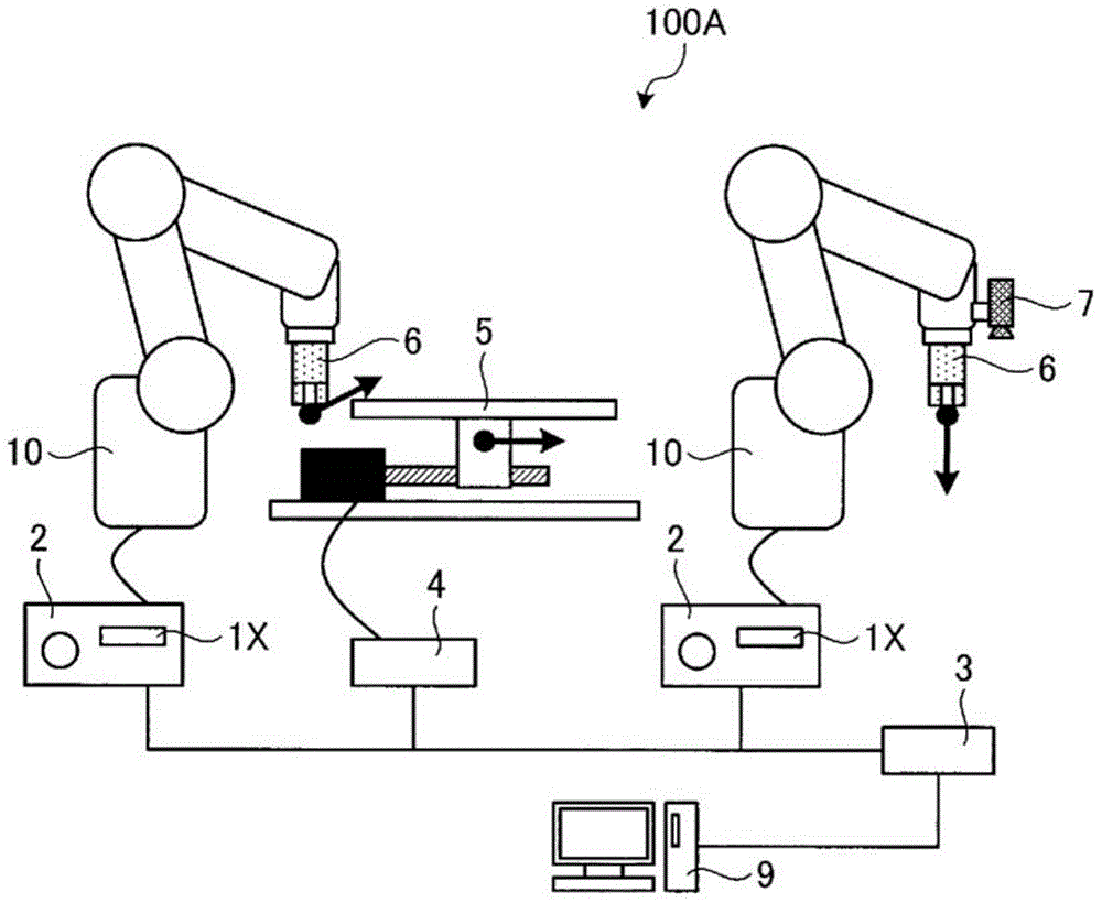
[0032] figure 1 It is a diagram showing the configuration of an interference checking system including the interference checking device according to the first embodiment. The interference checking system 100A is a system that includes the following components: a robot production system; a communication device 3 that connects devices in the robot production system; and a computer 9 that configures the controllers included in the robot production system. Make changes. In addition, the interference checking system 100A may include a control device such as a PLC (Programmable Logic Controller) instead of the communication device 3 , wherein the PLC has a communication function and a function of sending command values ​​and signals to each device.

[0033] The communication device 3 performs communication within the interference checking system 100A using Ethernet (registered trademark) or the like. Specifically, the communication device 3 communicates with the robot controller 2...

Embodiment approach 2

[0138] Next, use Figure 10 Embodiment 2 of the present invention will be described. In Embodiment 2, instead of inputting the model upper limit from the model number upper limit input unit 12, the model upper limit 102 is derived based on the limit value (allowable model remaining 113) for the model remaining 104 in the interference checking device. Number 102 way.

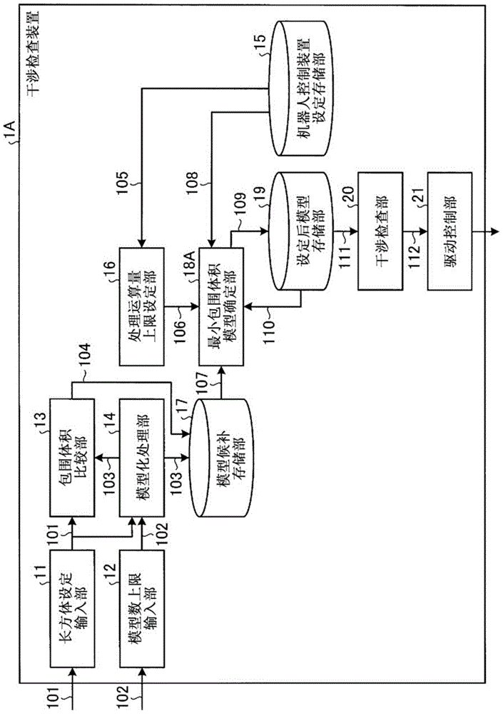
[0139] Figure 10 It is a block diagram showing the configuration of the interference checking device according to the second embodiment. Here, the configuration of an interference inspection device 1B as an example of the interference inspection device 1X will be described. exist Figure 10 Among the structural elements of the figure 2 Components having the same functions in the interference checking device 1A according to the first embodiment shown are denoted by the same reference numerals, and redundant descriptions are omitted.

[0140] The interference checking device 1B includes a cuboid setting inp...

Embodiment approach 3

[0151] Next, use Figure 11 ~ Figure 13 Embodiment 3 of the present invention will be described. In Embodiment 3, the generation part (part of the modeling processing part 14) of the cuboid used when the user performs modeling processing is automated by using 3D CAD (Computer Aided Design) information.

[0152] Figure 11 It is a diagram for explaining division processing for each set (module) using a CAD / CAM system. The modeling processing unit 14 of the present embodiment includes a CAD / CAM (CAD / CAE) system. The modeling processing unit 14 divides a pre-created three-dimensional model into a plurality of sets, and automatically converts each set into a cuboid model. exist Figure 11 3D model 81 shows a 3D model (modeled object) before conversion, and 3D model 82 shows a 3D model after converting each set into a cuboid model.

[0153] Figure 12 It is a block diagram showing the configuration of the interference checking device according to the third embodiment. Here, ...


PUM


Abstract

This interference check device (1A) is provided with: a model count upper limit input unit (12) to which is input the model upper limit count for geometric models set to a modelling subject that is the subject of an interference check; a modelling processing unit (14) that generates model candidates from the modelling subject using no more than the model upper limit count of geometric models; a processing-computation-volume upper limit setting unit (16) that sets the computation upper limit volume for the interference check on the basis of the computational processing volume required for each process of a controller that controls the modelling subject; a smallest-contained-volume model determination unit (18A) that determines the model candidate having the smallest contained volume of the model to be the modelling subject model among the model candidates subjected to the calculation process of the interference check at no greater than the computation upper limit volume; and an interference check unit (20) that performs the interference check between models using the determined model.

Description

technical field [0001] The present invention relates to an interference checking device for checking interference between robots or between robots and peripheral equipment. Background technique [0002] The interference check device is a device that checks the possibility of a collision for the purpose of preventing a collision between an industrial robot and its peripheral equipment in advance. The interference checking device checks the possibility of collision in advance, and when there is a possibility of collision, outputs an appropriate command value (command value for stopping or correcting the motion trajectory) to the robot, thereby preventing collision in advance. In particular, for an interference inspection device that performs inspections online even when the robot is in operation, instead of maintaining the original delicate shape of the industrial robot and its peripheral equipment, it is temporarily replaced with one that is easy to detect interference at hig...

Claims


Application Information

Patent Timeline
Patent Type & Authority Applications(China)
IPC IPC(8): G05B19/18B25J19/06
CPCB25J9/1666G05B2219/39094Y10S901/02Y10S901/49B25J9/1676G05B17/02
Inventor 白土浩司
Owner MITSUBISHI ELECTRIC CORP
Why Eureka
Try Eureka