Supercharge Your Innovation With Domain-Expert AI Agents!

Rubber roller structure of coating machine

A coating machine and rubber roller technology, which is applied to devices and coatings for coating liquid on the surface, can solve problems such as non-adherence of raw materials, and achieve the effects of improving production efficiency, reducing production costs, and being easy to popularize on a large scale.

Inactive Publication Date: 2015-10-14
WUXI ZHONGYI FILM TECH
View PDF0 Cites 0 Cited by
  • Summary
  • Abstract
  • Description
  • Claims
  • Application Information

AI Technical Summary

Problems solved by technology

[0004] The technical problem to be solved by the present invention is to overcome the existing defects and provide a coating machine rubber roller structure, which can solve the problem of non-bonding of raw materials

Method used


Image

  • Rubber roller structure of coating machine

Examples


Embodiment Construction

[0014] The preferred embodiments of the present invention will be described below in conjunction with the accompanying drawings. It should be understood that the preferred embodiments described here are only used to illustrate and explain the present invention, and are not intended to limit the present invention.

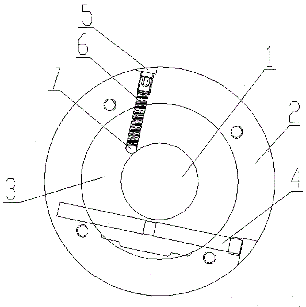
[0015] like figure 1 A coating machine rubber roller structure is shown, including a roller shaft 1, a roller seat 2, a roller cover 3, a pressure roller seat 5, a pressure roller fixing rod 6 and a pressure roller 7, and the roller seat 2 is fixed with a roller cover 3; A roller shaft 1 is fixed inside the roller cover 3; a pressure roller seat 5 is fixed on the edge of the roller seat 2; one end of the pressure roller fixing rod 6 is connected to the pressure roller 7, and the other end of the pressure roller fixing rod 7 is connected to Roller seat 5; the cross-sections of the roller shaft 1, the roller seat 2, and the roller sleeve 3 are circular; The fixed rod...


PUM


Abstract

The invention provides a rubber roller structure of a coating machine, wherein the rubber roller structure includes a roller shaft, a roller base, a roller sleeve, a press roller base, a press roller fixing rod and a press roller. The roller sleeve is fixed on the roller base. The roller shaft is fixed in the roller sleeve. The press roller base is fixed on the edge of the roller base. The press roller is connected to one end of the press roller fixing rod and the press roller base is connected to the other end of the press roller fixing rod. In the rubber roller structure of the coating machine, by means of the novel rubber roller structure, a raw material can be attached to the roller better, so that the rubber roller structure can increase production efficiency and reduce the production cost of enterprises, is reasonable in design, is accurate in positioning, is low in purchase cost and is easy to popularize in large scale.

Description

technical field [0001] The invention relates to the field of coating machine accessories, in particular to coating machine rubber rollers. Background technique [0002] Usually, if the strip material from the unwinding device is directly coated, the coating thickness or coating length may be uneven due to the change of the tension of the strip material, so a pressure roller (commonly known as a rubber roller ) is used to cut off the tension, the feeding roller and the pressure roller cooperate to form a pair of pinch rollers, so that the strip material from the discharge device first passes between the two, and then the strip material is transferred to the coating roller through the guide roller , The surface coating of the strip material is carried out by the coating head arranged on one side of the coating roller, which will make the strip material passing through the coating roller have a relatively uniform tension and improve the coating effect. [0003] However, the ra...

Claims


Application Information

Patent Timeline
Patent Type & Authority Applications(China)
IPC IPC(8): B05C1/08B05C11/00
Inventor 吴雄燕
Owner WUXI ZHONGYI FILM TECH
Features
  • R&D
  • Intellectual Property
  • Life Sciences
  • Materials
  • Tech Scout
  • Unparalleled Data Quality
  • Higher Quality Content
  • 60% Fewer Hallucinations
Learn More