
Cutting machine

A technology of cutting machine and locking mechanism, which is applied in the direction of metal sawing equipment, sawing machine, metal processing equipment, etc., can solve the problems of limited adjustment distance, cutting machine cannot meet the cutting requirements, and the thickness range of the workpiece can be processed is small, etc., to achieve The effect of meeting cutting needs

Active Publication Date: 2015-10-14
POSITEC MACHINERY ZHANGJIAGANG
View PDF5 Cites 9 Cited by
  • Summary
  • Abstract
  • Description
  • Claims
  • Application Information

AI Technical Summary

Problems solved by technology

However, since the pressing plate assembly is fixed on the workbench, although the distance between the workpiece pressing plate and the workbench can be adjusted, due to the limited adjustment distance, the thickness range of the workpiece that can be processed is small, so this cutting machine cannot meet different cutting requirements. need

Method used


Image

  • Cutting machine
  • Cutting machine
  • Cutting machine

Examples


Embodiment Construction

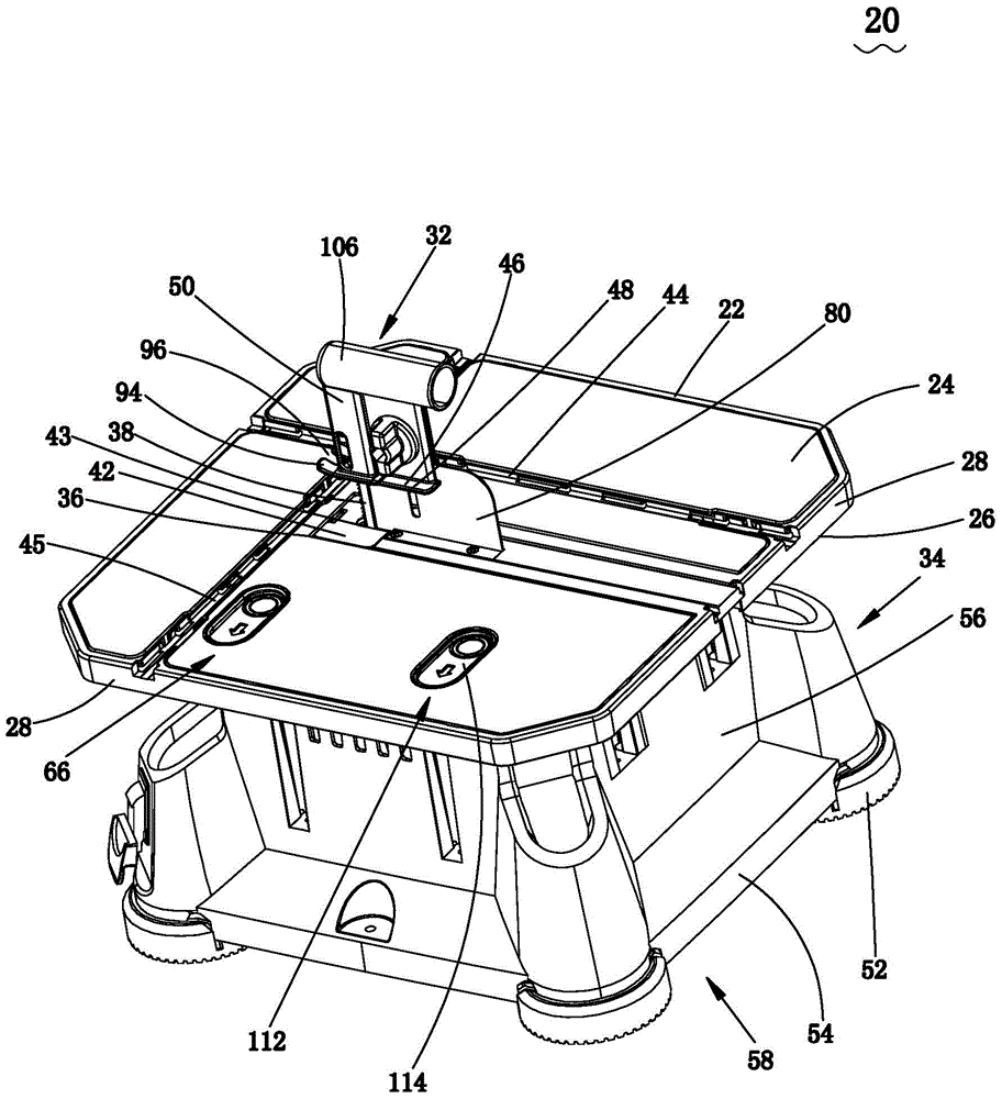
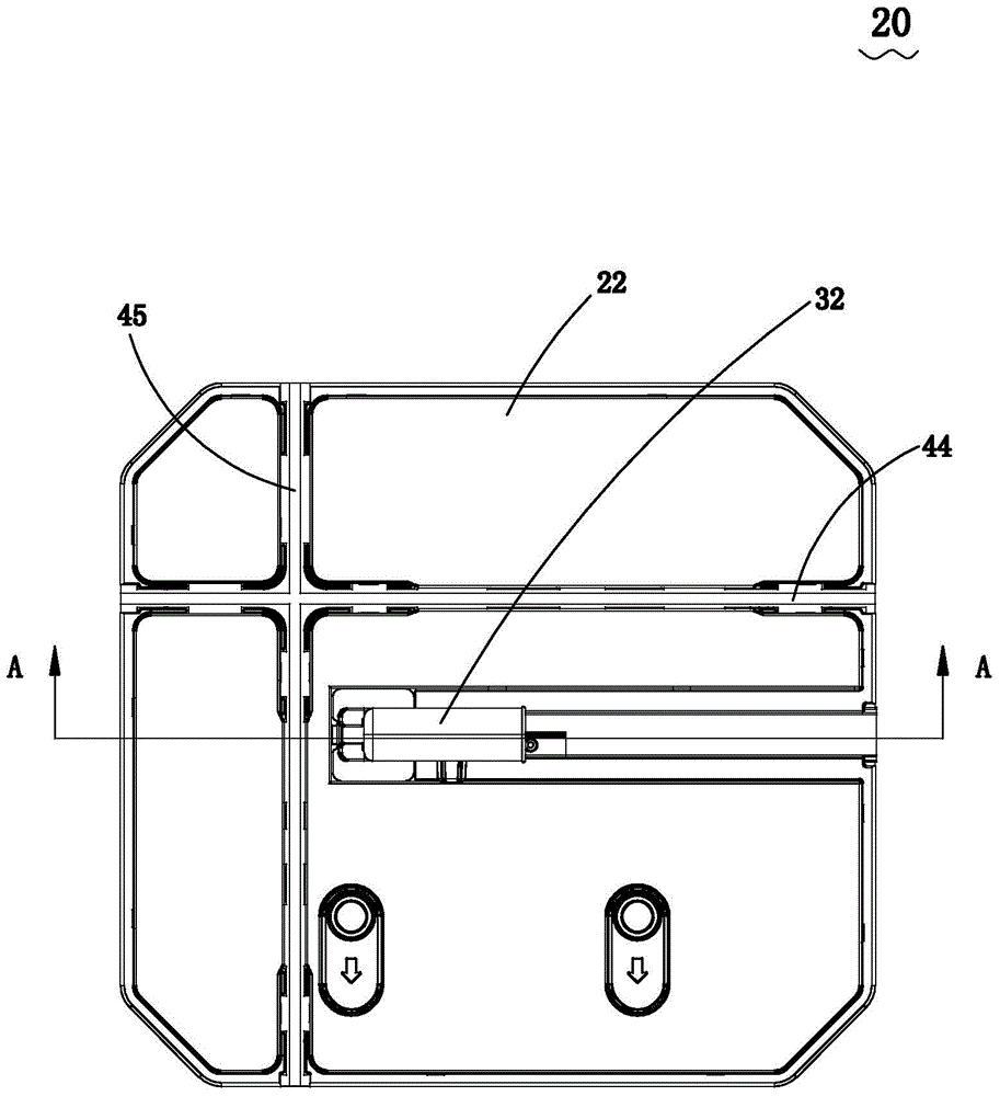
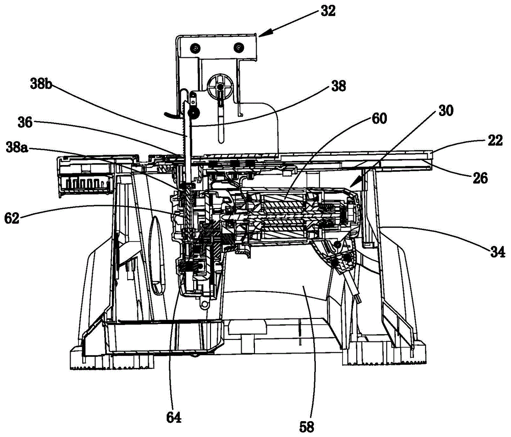
[0068] See attached Figure 1-3 , a cutting machine 20, including a table 22, the table 22 has an upper surface 24, a lower surface 26, and a side wall 28 extending vertically relative to the upper and lower surfaces 24,26. The upper surface 24 is used to support the workpiece.

[0069] The cutting machine 20 also includes a cutting mechanism 30 fixed on the lower surface 26 of the table 22, and a first platen assembly 32 disposed on the table 22, the first platen assembly 32 is used to exert a certain pressure on the workpiece. The support 34 is disposed under the workbench 22 for supporting the workbench 22 .

[0070] The opening 36 is defined on the workbench 22 and penetrates from the upper surface 24 to the lower surface 26 . The saw blade 38 passes through the opening 36 from bottom to top. A workpiece (not shown) may be placed on the upper surface 24 of the table 22 along which the workpiece is moved past the saw blade 38 to be cut by the saw blade 38 . The shape of...


PUM


Abstract

The invention relates to a cutting machine. The cutting machine comprises a worktable with an opening, a cutting mechanism fixed to a lower surface of the worktable and pressing plate components detachably arranged on the worktable, wherein the worktable comprises an upper surface used for supporting workpieces; the cutting mechanism comprises a motor used for outputting rotary motion, a reciprocating rod used for driving a saw to go through the opening to do reciprocating motion and a motion transformation mechanism used for transforming rotary driving of the motor into reciprocating motion of the reciprocating rod; and each pressing plate component comprises a workpiece pressing plate, and the workpiece pressing plate is provided with a pressing plate plane which is perpendicular to the upper surface and used for pressing the workpieces. According to the cutting machine, different pressing plate components can be conveniently and quickly replaced or dismounted according to different specifications of the cut workpieces or different cutting requirements.

Description

technical field [0001] The invention relates to a cutting machine with a reciprocating cutting mechanism. Background technique [0002] Existing jigsaws can perform various curved and straight cuts, and are therefore widely used in processing boards of various materials. Generally, a jigsaw includes a motor, a housing housing the motor, a motion conversion mechanism housed in the gear box housing, driven by the motor and converting the rotational motion of the motor into the reciprocating motion of the reciprocating rod, and connected to the reciprocating rod through a chuck device The saw blade, and the bottom plate that supports the body of the jigsaw on the surface of the workpiece. [0003] In order to expand the application of the jigsaw, the technicians in the industry place it upside down on the lower surface of a work table so that it can be cut by moving the workpiece. The existing upside-down jigsaw is usually to directly turn over the jigsaw sold on the market, ...

Claims


Application Information

Patent Timeline
Patent Type & Authority Applications(China)
IPC IPC(8): B23D51/04B23D51/00
Inventor 沃伦·布朗哈利·索默格雷厄姆·格哈德
Owner POSITEC MACHINERY ZHANGJIAGANG
Learn More