
Motor braking device of electric bicycle back-pedal brake mechanism

A technology of electric bicycles and brake mechanisms, applied in the direction of bicycle brakes, bicycle accessories, vehicle parts, etc., can solve problems such as increasing production costs, increasing assembly processes, and reducing equipment reliability, so as to simplify assembly processes, improve safety, and respond fast effect

Active Publication Date: 2015-10-14
SUZHOU SHENGYI MOTOR
View PDF7 Cites 4 Cited by
  • Summary
  • Abstract
  • Description
  • Claims
  • Application Information

AI Technical Summary

Problems solved by technology

[0006]1) When there is no reliable misalignment between the crankshaft (bottom shaft) drive ring and the sprocket (chainring) sleeve that respectively hold the two magnets, or When the misalignment is not obvious due to long-term wear and tear, the amount of change in the magnetic flux generated between the magnets is very small, and the Hall element (magnetic sensor) cannot accurately detect the weak magnetic induction signal, and it cannot brake the motor in a timely and effective manner.
Therefore, in general, the induction sensitivity and reliability of the magnetic induction element in this mechanism are relatively poor.
[0007]2) The magnets on both sides of the induction are non-closed structures, and the two magnets are exposed to the pedal area for a long time. The magnetic induction intensity between them affects the working reliability of the whole mechanism
[0008]3) The drive ring of the intermediate part is designed, which is connected with the keyway of the crankshaft, which not only increases the assembly process, but also increases the production cost, and once the assembly deviates, it will It will affect the work of the whole mechanism, so the reliability of the equipment is reduced to a certain extent

Method used


Image

  • Motor braking device of electric bicycle back-pedal brake mechanism
  • Motor braking device of electric bicycle back-pedal brake mechanism
  • Motor braking device of electric bicycle back-pedal brake mechanism

Examples


Embodiment

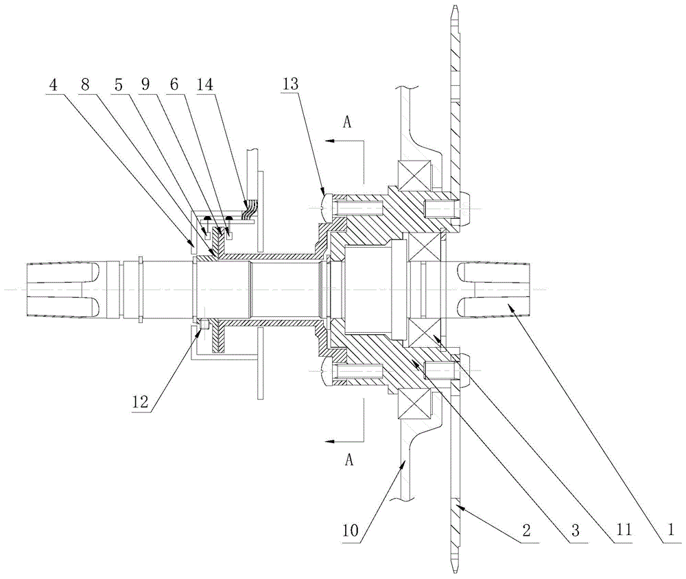
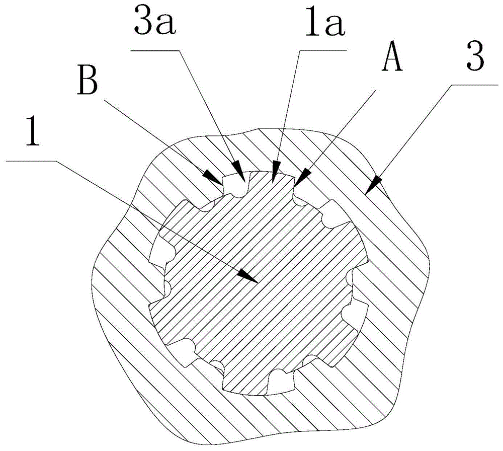
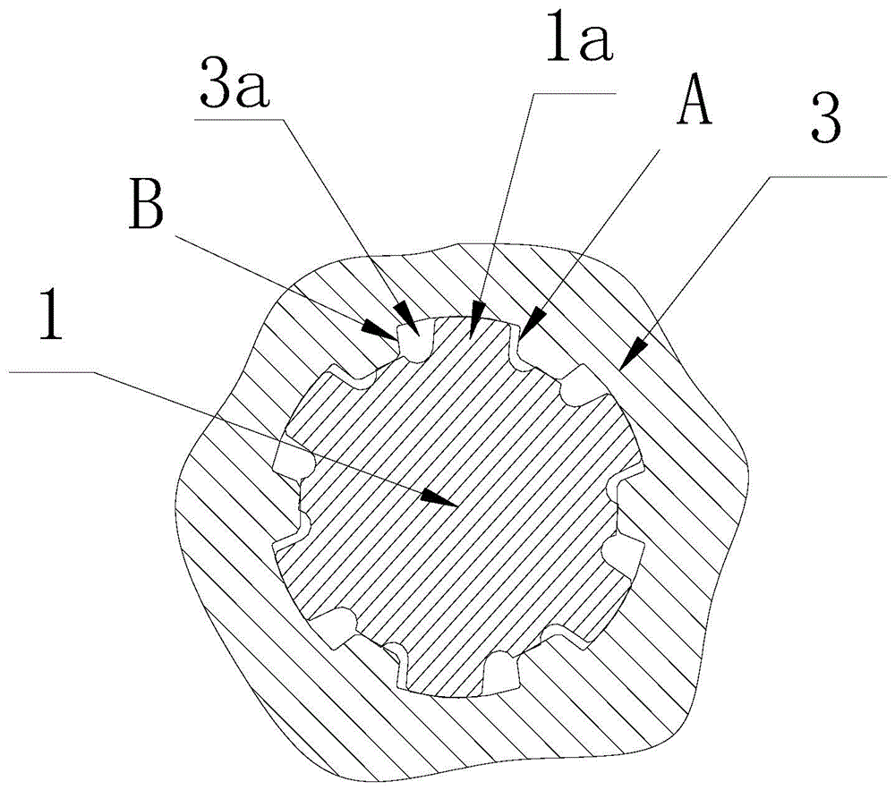
[0037] Example: Combine Figure 1~Figure 7 As shown, the specific implementation of the motor brake device of the electric bicycle reverse pedal brake mechanism of the present invention will be described. This embodiment is specifically assembled on an electric bicycle that adopts a central motor, such as figure 1 As mentioned above, its conventional structure is: vehicle frame (not shown in the figure), central shaft 1 installed on the vehicle frame and central motor (omitted in the figure), as in the prior art, the central motor and central shaft 1 are connected and transmitted through a gear reduction mechanism, and the housing 10 of the central motor is fixed to the vehicle frame; a chain disc 2 is also arranged on the central shaft 1, and the chain disc 2 is connected to the brake mechanism installed on the wheel hub through a chain (in the figure omitted) connected. The core improvement of the present invention is as follows:

[0038] The chain disc 2 is connected to ...


PUM


Abstract

The invention discloses a motor braking device of an electric bicycle back-pedal brake mechanism. A mechanical part is designed with a middle shaft and a chain disk connecting frame which are in radial clearance rotating fit so that when the back-pedal middle shaft rotates reversely, the middle shaft and the chain disk connecting frame can carry out nonsynchronous relative rotation. A circuit part uses a photoelectric sensor, and the core is a luminophor designed in a camera obscura, a photosensor and a shading component controlled by the mechanical part. When a person pedals a bicycle backwards, the middle shaft drives the chain disc connecting frame to rotate reversely after certain delaying, in the process, a middle shaft shading body in the shading component and a light hole or a gap in a chain disk shading body changed to be overlapped from being staggered so that light rays emitted out by the luminophor can penetrate and be received by the photosensor, and then signals are emitted to brake a motor. Compared with an existing related magnetic induction braking products, the sensitivity and the reliability are high, the motor can be effectively braked, and cogent guarantee is provided for executing of back-pedal braking on the electric bicycle.

Description

technical field [0001] The invention relates to a motor brake device of a reverse pedal brake mechanism of an electric bicycle. Background technique [0002] The reverse pedal brake mechanism is a mechanism that uses the pedal to produce a braking effect, that is, when the chain is reversed by the crank, it is linked with the brake mechanism installed in the hub axle, thereby producing the action of braking the rear wheel. This kind of brake mechanism was used more on old-fashioned traditional bicycles in the past. At present, it is relatively rare in our country, but there is still a great demand in some countries and regions, and some of them are also used as the standard of bicycle safety brake brake mechanism. . [0003] With the widespread promotion and development of electric (power-assisted) bicycles around the world, the above-mentioned reverse braking mechanism will naturally be applied to some electric bicycles. However, there are the following problems in moving ...

Claims


Application Information

Patent Timeline
IPC IPC(8): B62L5/00B62M6/50
Inventor 温群峰
Owner SUZHOU SHENGYI MOTOR
Learn More