
Fuel injector

A fuel injector and fuel injection technology, applied in fuel injection devices, charging systems, combustion engines, etc., can solve problems such as fluctuations and deterioration

Inactive Publication Date: 2015-10-14
DENSO CORP
View PDF11 Cites 0 Cited by
  • Summary
  • Abstract
  • Description
  • Claims
  • Application Information

AI Technical Summary

Problems solved by technology

Therefore, the fluctuation of the air-fuel equivalence ratio in the combustion chamber deteriorates

Method used


Image

  • Fuel injector
  • Fuel injector
  • Fuel injector

Examples


no. 1 example

[0022] A first embodiment of the present invention will be described.

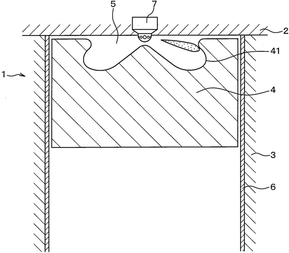
[0023] Such as figure 1 As shown, an internal combustion engine 1 comprises a cylinder head 2 , a cylinder block 3 and a piston 4 which form a combustion chamber 5 . According to this embodiment, the internal combustion engine 1 is a compression ignition type internal combustion engine.

[0024] A cylinder liner 6 is provided on the inner peripheral portion of the cylinder block 3 . The top of the piston 4 is provided with a cavity 41 which is part of the combustion chamber 5 .

[0025] The fuel injector 7 is placed at a position of the cylinder head 2 adjacent to the central axis of the combustion chamber 5 . The fuel injector 7 is connected to a common rail (not shown) accumulating high-pressure fuel and injects the high-pressure fuel into the combustion chamber 5 . Specifically, the fuel injector 7 injects high-pressure fuel supplied from the common rail into the cavity 41 .

[0026] Such as figu...


PUM


Abstract

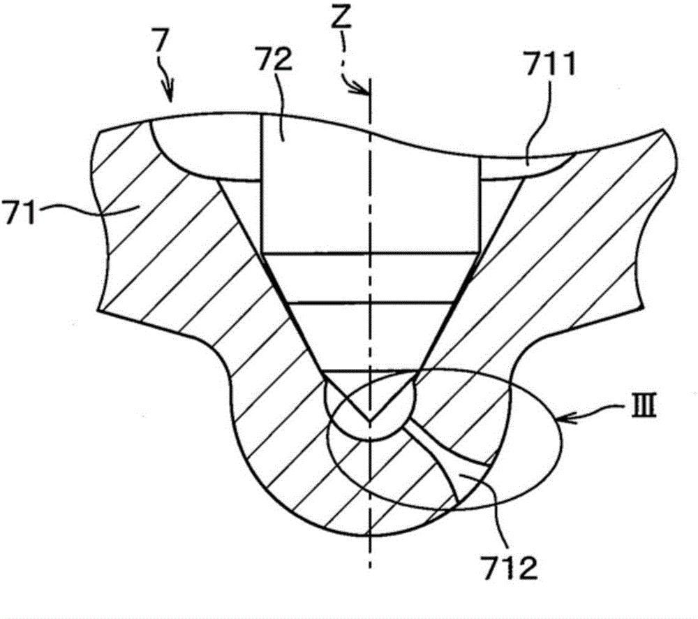
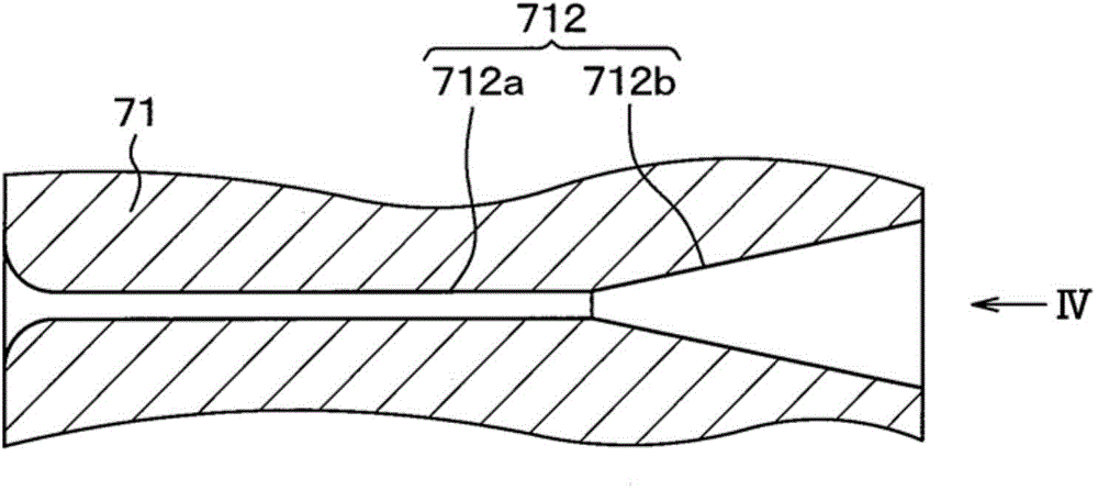
An injection port includes a straightening area which straightens a flow of a fuel, and an increasing area which is a slit connected to a downstream end of the straightening area and increasing a cross-sectional area of the flow toward a downstream end of the increasing area. The fuel is injected from the downstream end of the increasing area. When a cross-sectional area of the downstream end of the straightening area is expressed as S1, a cross-sectional area of the downstream end of the increasing area is expressed as S2, and a shape property value is expressed as X that is equal to S2 / S1, the shape property value X is set to be greater than 1.0 and be less than or equal to 4.0.

Description

technical field [0001] The invention relates to a fuel injector for injecting fuel into a combustion chamber of an internal combustion engine. Background technique [0002] Conventionally, the first fuel injector has a constant inner diameter, or the first fuel injector is a frusto-conical shape with a decreasing diameter downstream of the fuel. [0003] Alternatively, according to JP-2005-131539A, the second fuel injector includes an injection port having an inner wall surface provided with a spiral-shaped protrusion. Fuel flowing through the injection port becomes swirl fuel and is injected as a spray with a larger spray width. [0004] However, since the spray width of the spray of fuel injected from the first fuel injector is small, it is difficult for the fuel to diffuse to fill the combustion chamber. Therefore, fluctuations in the air-fuel equivalence ratio in the combustion chamber deteriorate. Moreover, due to the small spray width, the spray penetrating power is...

Claims


Application Information

Patent Timeline
IPC IPC(8): F02M61/18
CPCF02M61/182F02M61/14F02M61/184F02B23/0648F02B23/0669F02M61/1833F02M61/1846F02B23/0672Y02T10/12
Inventor 芹泽一史铃木雅幸石塚康治
Owner DENSO CORP
Learn More