
Porous-iron-core-structure micro-fluxgate sensor

A fluxgate sensor, porous structure technology, applied in the magnetic field measurement, the size/direction of the magnetic field and other directions using the magnetic flux control principle, can solve the problems of low current efficiency, serious magnetic leakage, reduction, etc., to reduce the excitation current, The effect of reducing power consumption and improving efficiency

Inactive Publication Date: 2015-10-14
NORTHWESTERN POLYTECHNICAL UNIV
View PDF5 Cites 9 Cited by
  • Summary
  • Abstract
  • Description
  • Claims
  • Application Information

AI Technical Summary

Problems solved by technology

[0004] However, the variable cross-sectional area iron core structure miniature fluxgate excitation coil and induction coil described in the literature are located at different positions of the iron core and the distance is far away. Severe magnetism and low current efficiency hinder the further reduction of sensor power consumption

Method used


Image

  • Porous-iron-core-structure micro-fluxgate sensor
  • Porous-iron-core-structure micro-fluxgate sensor
  • Porous-iron-core-structure micro-fluxgate sensor

Examples


Embodiment 1

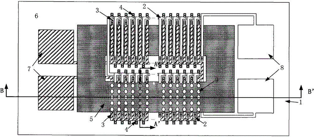
[0028] Example 1: Micro Fluxgate with Honeycomb Holes

[0029] Refer to attached figure 1 , 2, 3, The microfluxgate sensor with porous iron core structure in this embodiment includes a silicon substrate with a silicon dioxide insulating layer to provide support for the entire structure. Double iron core structure is adopted, the two ends of the iron core are connected to form a ring shape, and the iron core has hexagonal holes arranged densely in the vertical iron core axis and spaced apart in the parallel iron core axial direction. These holes divide the iron core into Multiple sets of local variable cross-sectional area structures. Such an iron core layer is surrounded by a three-dimensional solenoid excitation coil and an induction coil perpendicular to it, and polyimide is used as an insulating layer and a protective layer between the induction coil and the iron core. The induction coil and the excitation coil are respectively connected to pads on the substrate.

[003...

Embodiment 2

[0049] Embodiment 2: Miniature Fluxgate with Square Hole

[0050] Refer to attached Figure 5 , 6, 7, The micro-fluxgate sensor with porous iron core structure in this embodiment includes a silicon substrate with a silicon dioxide insulating layer to provide support for the entire structure. Double iron core structure is adopted, the two ends of the iron core are connected to form a ring shape, and the iron core has hexagonal holes arranged densely in the vertical iron core axis and spaced apart in the parallel iron core axial direction. These holes divide the iron core into Multiple groups of local variable cross-sectional area structures. Such an iron core layer is surrounded by a three-dimensional solenoid excitation coil and an induction coil perpendicular to it, and polyimide is used as an insulating layer and a protective layer between the induction coil and the iron core. The induction coil and the excitation coil are respectively connected to pads on the substrate. ...


PUM

PropertyMeasurementUnit
lengthaaaaaaaaaa
widthaaaaaaaaaa
thicknessaaaaaaaaaa

Abstract

The invention discloses a micro-fluxgate sensor having a porous iron core. A silicon substrate (1) serves as a substrate supporting layer; an excitation coil (2) and an induction coil (3) adopt a three-dimensional solenoid structure, and upper and lower layers are communicated through two-end through holes (4); an iron core (5) adopts a soft magnetic material and a porous structure, and holes in the iron core separate the iron core into a plurality of groups of local variable cross-section structures; polyimide (6) serves as an insulating layer between the layers respectively; the excitation coil and the induction coil are wound alternatively in a manner that the excitation coil is corresponding to the nonporous places, and the induction coil is corresponding to the porous places; and the excitation coil and the induction coil are led out through bonding pads (7,8). The micro-fluxgate sensor can effectively reduce power consumption of a micro-fluxgate, and sensitivity is improved.

Description

Technical field: [0001] The invention relates to a fluxgate sensor, in particular to a miniature fluxgate sensor prepared by micro-electromechanical (MEMS) technology. Background technique: [0002] Fluxgate is a magnetic field component sensor with very good comprehensive performance. Miniaturized fluxgates have the characteristics of small size, light weight, and simple structure, but there are problems such as high power consumption and difficulty in heat dissipation due to small size and high power consumption. [0003] refer to Figure 9 , the document "A fully integrated ring-type fluxgate sensor based on a localized core saturation method. IEEE Transactions on Magnetic, 2007, 43(4): 1040-1043" discloses a miniature fluxgate with a variable cross-sectional area iron core structure sensor. The annular soft magnetic material is used as the iron core (1), and the cross-sectional area (2) of the iron core at the position corresponding to the induction coil is reduced to ...

Claims


Application Information

Patent Timeline
Patent Type & Authority Applications(China)
IPC IPC(8): G01R33/04
Inventor 刘诗斌郭博杨尚林
Owner NORTHWESTERN POLYTECHNICAL UNIV
Learn More