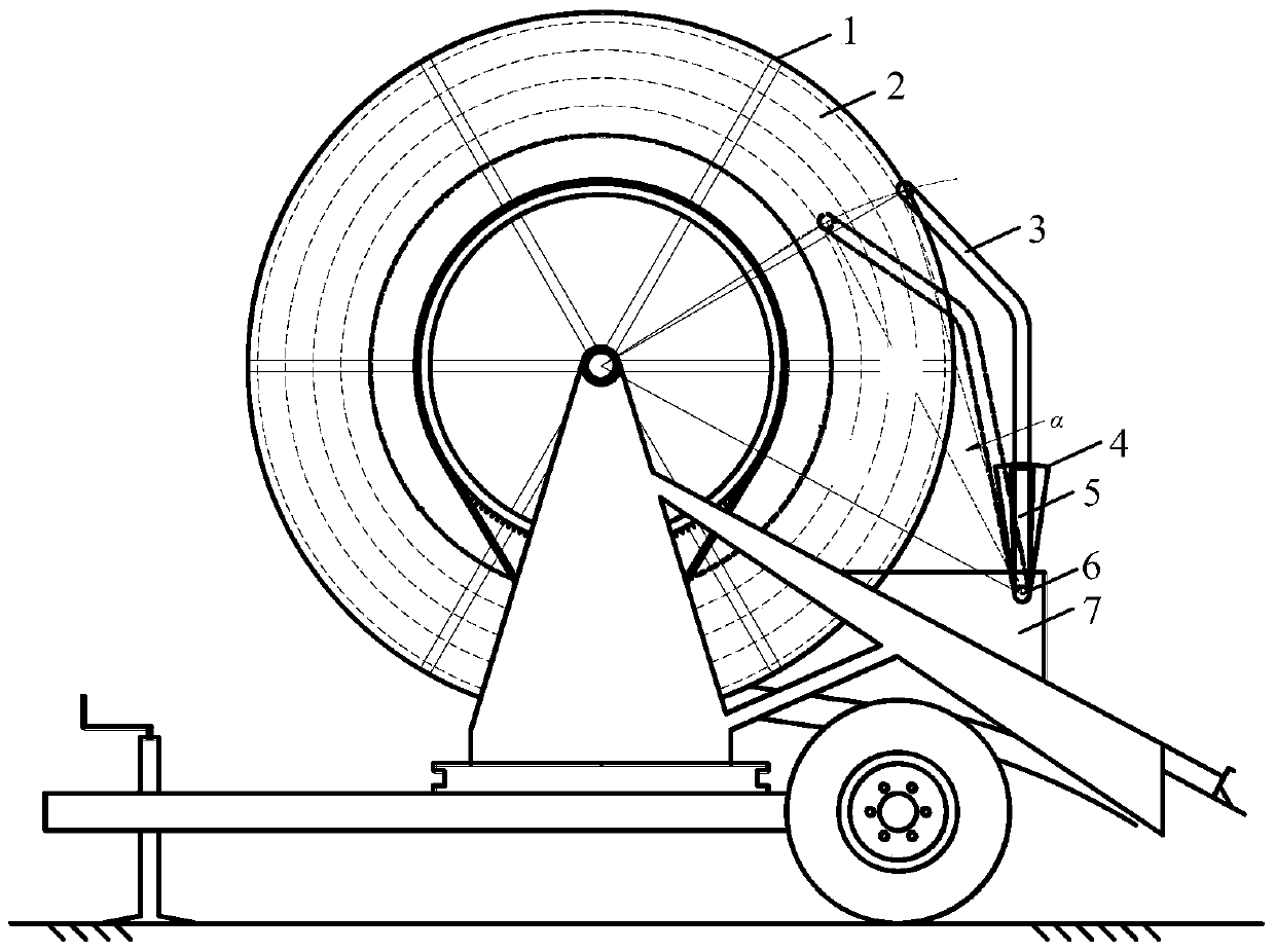
A detection device for the number of PE pipe layers of a reel type sprinkler irrigation machine
A detection device and sprinkler technology, applied in optical device exploration, etc., can solve problems such as incorrect judgment of PE pipe layers, loss of historical sensing information, low reliability, etc., to achieve direct and effective detection methods and strong anti-interference ability , high reliability effect
- Summary
- Abstract
- Description
- Claims
- Application Information
AI Technical Summary
Problems solved by technology
Method used
Image
Examples
Embodiment 1
[0041] The signal emitting device may be an infrared emitting tube, and the signal receiving device may be an infrared receiving tube.
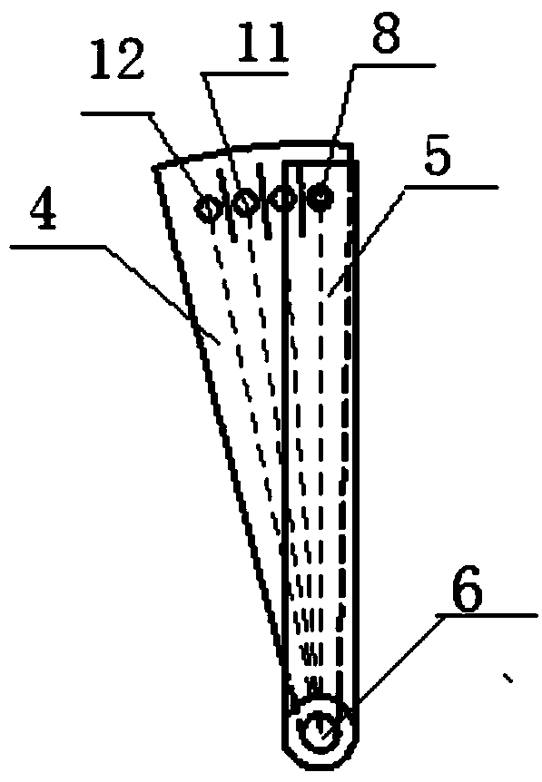
[0042] Such as Figure 2 to Figure 5 As shown, an infrared emission tube F is installed on the static sheet 5 1 8. The moving piece 4 is equipped with four infrared receiving tubes, and the four infrared receiving tubes are in turn infrared receiving tubes A 1 9. Infrared receiving tube A 2 10. Infrared receiving tube A 3 11. Infrared receiving tube A 4 12; the four infrared receiving tubes and the infrared emitting tube F 1 8 have the same radius on the circumference, and the position of the four infrared receiving tubes is opposite to the infrared emitting tube so that the four infrared receiving tubes can receive the infrared signals emitted by the infrared emitting tube. A partition 13 is arranged between the adjacent two infrared receiving tubes to prevent the adjacent infrared receiving tubes from receiving the infrared emitting tu...
Embodiment 2
[0045] The signal transmitting device and the signal receiving device are combined into a pair of photoelectric transceivers.
[0046] Such as Figure 6 to Figure 9 As shown, the moving plate 4 is installed with four pairs of photoelectric transceiver pairs along the circumferential direction, and the four pairs of photoelectric transceiver pairs are photoelectric transceiver pairs D in turn. 1 14. Photoelectric transceiver pair tube D 2 15. Photoelectric transceiver pair tube D 3 16 and photoelectric transceiver pair tube D 4 17. A partition 13 is provided between each pair of photoelectric transceiver pairs to prevent the adjacent photoelectric transceiver pairs from being interfered with each other when transmitting and receiving infrared signals. The transverse width of the static piece 5 can block a pair of photoelectric transceivers, and when the position of the moving piece 4 changes, the static piece 5 can reflect back the infrared signals emitted by the signal emit...
Embodiment 3
[0049] The signal transmitting device and the signal receiving device are combined into a pair of photoelectric transceivers.
[0050] Such as Figure 10 to Figure 13 As shown, two pairs of the photoelectric transceiver pair tubes are sequentially placed in the horizontal direction of the static sheet 5, and the photoelectric transceiver pair tubes are respectively the photoelectric transceiver pair tubes D 5 18 and photoelectric transceiver pair tube D 6 19. When the relative positions of the moving piece 4 and the static piece 5 are P1, P2, P3, and P4 in sequence, the moving piece 4 has a small hole 22 at the positions of P1 and P2 respectively, and the small hole 22 It is the same as the circumference radius of the photoelectric transceiver pair tube. The position of the small hole 22 corresponds to the position of the photoelectric transceiver pair tube. When the photoelectric transceiver pair tube overlaps the small hole 22, the signal emitted by the signal emitting dev...
PUM
 Abstract
Description
Claims
Application Information
 - R&D
- Intellectual Property
- Life Sciences
- Materials
- Tech Scout
- Unparalleled Data Quality
- Higher Quality Content
- 60% Fewer Hallucinations
Browse by: Latest US Patents, China's latest patents, Technical Efficacy Thesaurus, Application Domain, Technology Topic, Popular Technical Reports.
© 2025 PatSnap. All rights reserved.Legal|Privacy policy|Modern Slavery Act Transparency Statement|Sitemap|About US| Contact US: help@patsnap.com


